| Page Shortcuts: |
|---|
| The Options |
| The Hunt |
| Scanning Unit |
| Tuning Unit |
| Hickok Tube Tester |
| Scanning Unit, Again |
| Installation |
| The Verdict |
| Postscript |
|
|
| ||||||||||
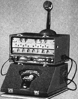
| Stroboconn 6T (file photo) |
I'd wanted one of these multi-dial strobe tuners for years, but they're not too easy to come by. I figured one would be a nice addition to our new music room. They'd pop up on eBay from time to time, but the working ones were always well above my budget for such a thing, not to mention the vicious shipping charge for something so bulky and heavy. Even the broken single-dial (read: portable) strobe tuners always went for more than I'd like to spend. (Well, I really didn't even want a single-dial strobe, we already have some single-readout tuners. What I wanted was one that'd show all the notes in parallel so that one could just play into it and see what was going on—instantaneous readout and no fiddling with settings. The multi-dial Stroboconn is pretty much the only game in town, they made them from 1936 to about 1976, so there are more than a few out there.) The Stroboconn is comprised of two units: the Scanner, which contains the neon-lit motor-driven dials and an audio amplifier to drive the neon tube, and the Tuner, which contains a precision high-power variable-frequency AC drive for the motor in the scanner. (This is all old-school tube technology, not solid-state.)
Stroboconn piano tuning handbook: http://www.terrysmythe.ca/Stroboconn_6T-3.pdfStroboconn manual, for the newer units.
Stroboconn schematic, for the older (6L6) tuning units.
Stroboconn 8T JR 1947 manual, for the cost-reduced non-tunable (line-referenced) version
Stroboconn Patent, schematics, drawings, theory of operation
Stroboconn Article in Radio Electronics, July 1951, by Richard H. Dorf
Single-dial Conn strobes (Strobotuners) have somewhat of a reputation for drifting out of calibration, but the Stroboconn doesn't. Because the Strobotuners need a switchable (and more importantly, adjustable!) reference frequency in order to tune all the notes it's difficult to design a circuit (pre-microprocessor and without benefit of quartz oscillators) that's particularly stable, without it being too large/heavy/expensive for the purpose. The single-frequency thermally-compensated adjustable tuning fork in the Stroboconn 6T is very stable; gears in the Scanner are used to derive the various notes from the single reference rather than using multiple reference frequencies. However there are obvious size/weight consequences, as the Stroboconn 6T is (or was) large, heavy, and expensive! ($700 in 1955, which would be $6,300 in 2017.)
The 8T Junior, lacking the tunable oscillator unit, should have been about half the price of the 6T. It uses the power line as a reference frequency, which in the US has historically been very good. In essence the 8T is just the 6T with the scanner motor fixed on the "warm" setting, but with a different primary gear in the gearbox so that the 60Hz motor drive (instead of the normal 55Hz) gives you A=440. Naturally you cannot adjust your A using the 8T. This was probably aimed at the burgeoning primary school band market, where such subtleties were not called for, and where the lower cost would help increase market penetration.
I considered the homebrew option. I toyed for awhile with the idea of using old SCSI hard disks to supply parts. (I got a large batch of them from work when they decomissioned some servers.) If I could tap into the platter motor drive circuitry, and apply the dial patterns to the platter, I could possibly make one. That would take some doing, however, and might turn out rather large and ugly. Better would be to get a real one that needed fixing.
Another option I considered was getting a trashed Stroboconn and, if required, replacing its electronics with more modern elements. My understanding is that the motor driver is approximately a 60W audio amplifier, one could easily flange up a crystal-controlled source driving, perhaps, a DC-AC inverter output stage. A stereo amplifier might also work, one channel for the motor, and one for the lamp drive. In the worst case an LED matrix could substitute for the neon lamp. None of this is something I'd prefer to do, but it would be a backup plan.
When it came it looked pretty good. Serial #913. The glass and paint were fine, though the transposition scale knob and the microphone were missing. The wooden case covers were included. The glop spilled inside might have been soup, or hot chocolate. Perhaps they were warming their lunch over the tubes? It was hard to tell from the residue what it might have been, and there was no scent left by this time. Whatever it was hit the power transformer and the tubes, but didn't seem to get into anything critical. It did not get down into the tube sockets or circuitry at all, nor into the high-voltage transformer. Both fuses looked good; the tubes were all intact.
The original power cord was gone, as is common with these, and the power socket (in the Scanning Unit) was destroyed and the socket's guts were missing. (The power socket is no longer a standard, and new cords are impossible to come by. Looks like something that might have been used on adding machines, etc.) They'd had some kind of power cord loosely wire-nutted into it, a real hack job. The special Hubbell three-terminal twist-lock interconnect cord, which really is unique, was there and in good shape. Good, no special problems yet.
I'm going to have some difficulty finding a style-matching and functional microphone. I believe this is intended to use a high-output crystal microphone, so it's possible that not just any mic will work well in its place. It could be converted to use a modern dynamic microphone, but that would probably require an additional preamplifier. Not attractive.
The microphone amplifier uses five tubes: a 5Y3 rectifier, a 6J7 input amplifier, a 6SC7 splitter/driver, and two 6V6 power output tubes. The 6V6's look like they push-pull into a high-voltage transformer for the neon tube. The HV output from the transformer goes into a coax cable, using something that looks like an old RCA phono jack's big brother. The cable itself is labeled Amphenol RG-54 A/U. Very straightforward design, and with the exception of the transformers and motor/gearbox it looks like everything else would be easy to repair or replace.
I took a dead wall-wart switching power supply, of the rat-in-a-snake variety, and removed its (now-standard) computer power supply power socket from the circuit board. By bending the leads towards the rear and sanding off the corners of the plastic I could get this socket to slip into the remains of the original power socket, whereupon I glued it into place with Shoe Goo. After this dried I wired it in, and I also hooked up the ground lead to a screw through a nearby chassis hole. Voila, instant detachable standard power cord, with a now-standard safety ground.
With power now available I started probing around. I couldn't get power to the two spade terminals that feed the microphone amplifier, so I checked the power switch. It was high-resistance when ON, so I used brake cleaner to clean it and the warm-up switch. That fixed the high resistance problem, but I still couldn't get power to the spade lugs. I checked the fuse and it seemed OK, but when I removed the fuse holder the output-side lug fell off the bottom! The rivet had broken. I used a small self-tapping screw to attach the clip to the terminal again and finally there was power continuity to the spade terminals.
I laid out the amplifier so it could be powered while still accessing the circuitry on the bottom and plugged in the high-voltage coax cable for the neon tube. In accordance with standard practice for resurrecting old tube gear I got a Variac from the workbench and hooked everything up, then applied about 20 V to the unit and turned it on. No explosions, and after a bit I got a few volts on the main filter capacitor. I raised it to 30 V and got a bit more on the capacitor. When I turned off the warm-up switch the power to the amplifier was cut, but the motor started turning feebly. (Apparently line power is used to supply motor starting current, that probably eases the cut over to the Tuning Unit.) Over the next couple of hours I raised the voltage 5 V at a time until I was applying full power. (This was to re-form the possibly long-idle electrolytic filter capacitors.) At some point the 6J7's floating grid cap (the amplifier's input) picked up enough ambient 60 Hz noise that the neon tube started flickering. Excellent!
At full line voltage the B+ voltage on the amplifier is about 350 V. There was no sign of the electrolytic capacitors failing, though I'm sure that they could stand replacement. (There are two cans, and they're both doubles.) The neon light is nice and bright, and responsive to a fingertip on the input tube's grid cap. The motor spins readily when on the warm-up setting. When I get some formal instructions on how to lubricate the motor and gear train I will do so, but I hesitate to just start glopping oil around everywhere. Time to put the Scanning Unit back together and move on to the Tuning Unit.
The electric tuning fork is a nice bit of mechanical engineering, it's large and occupies a substantial portion of the front (sloped) part of the case. Two electromagnets drive it, and the tuning knob runs a band-driven mechanism that slides weights out along the tines.
I removed the tubes from the Tuning Unit, then removed the amplifier chassis from the case. I washed off the tubes, and then used a rubber mallet and the extension socket to straighten the chassis and the mounting ears of the power transformer. One of the terminal strips was broken underneath, so I glued it. Once the glue had set up a bit I connected the amplifier back up, but laying sideways so that I could access the bottom components. I then hooked up the Variac and started bringing up the power slowly so that the electrolytics could re-form if they needed it.
The B+ voltage gradually worked up to 500 V—a bit high considering that the two paralleled 4 µF main filter capacitors are rated at 600 V. Above about 450 V the motor pilot light would spontaneously flash occasionally, and you could force it on for a bit by tapping the tuning fork. When the light was on the B+ would drop down to about 475 V, but the oscillation wouldn't sustain and insufficient output power was developed to turn the motor. On the AC setting the Fluke 87 measured 24 VAC of 120 Hz ripple on the main filter capacitors when the pilot light was lit, less when it was not. There's something wrong, probably either a weak tube or a fading capacitor. Further research will be required.
Time to get out the big guns. I dug my Tektronix 2336 oscilloscope out of its nest on the bench. The scope's input is rated 400 V, not sure if that's using a 10× probe or not, so I used my Tek P6015A 1000× high-voltage probe just to be safe. (Normally used to measure TV picture tube anode voltages.) The B+ ripple voltage is real, so I re-formed an old 450 V junkbox capacitor to see if added capacitance would help, but it couldn't take the voltage and arced when I hooked it up. I couldn't find anything else, even the input capacitor from a universal switching power supply was only rated at 400 V. I hooked up a Fluke to the nominal output of the motor drive and found that when the forks are plucked the output goes to 115 VAC at 55 Hz, with the frequency dial centered. It holds for a second or so, then fades away. (Low gain?) The frequency range of the fork seems to be 53–56.5 Hz.
A mistake with the probing during an attempt to monitor the output waveform with the scope resulted in a blown circuit breaker and big chunks out of one of the terminal strips and the ground clip of my oscilloscope probe. Oops! (Variacs are autotransformers and don't isolate the output from the line. Enough screwing around. I unshipped the Variac with the integral isolation transformer from the bench and brought it in too. Much safer!) The amplifier output looks sort of like a sine wave, with a decaying amplitude and a mildly deformed waveform that shifts a bit as it decays from the pluck.
It's probably time to test the tubes. Fortunately I have a tube tester that I got at the thrift shop a few years ago.
Hickok Tube Tester
I dug the Hickok 600A tube tester out of storage, but its meter didn't seem to be working. (I checked the web, and it turns out that the 600A is on the more desirable end of the scale.) I opened it up to have a look. Two tubes (a #83 mercury-vapor rectifier and a 5Y3 rectifier), a multi-tapped power transformer, a whole lot of switches, and some potentiometers. (The #83 provides plate power for the DUT, the 5Y3 provides the bias voltages. [I was later told that this tester should have a 5Y5G, which is "10 V different" from the 5Y3GT which will make for incorrect readings. Other online references state that it is indeed a 5Y3 used in most Hickoks, and specifically in my 600A.]) I used brake cleaner on all the switches, and I pulled the tubes out and reseated them. After that it seemed to work, sort-of, but it claimed that all four 6V6/6L6 tubes I checked (same tester settings) were weak, though approximately equally. I suspected that the tester was wrong. Too bad it didn't come with instructions! Still, even if the absolute values are wrong one could at least still do some qualitative testing.The tester's #83 tube is looking fogged on the inside now. It was beautifully clear before I started trying to use the tester. It probably got gassy over the years, and is now burning up with power applied. I'll need another one, I guess. Rumor has it, though, that #83 tubes are becoming scarce and expensive, so I might pursue a solid-state replacement. (One supplier wants $36 for one, and says that it's a low-drop rectifier with some voltage-regulating capability.) The same rumor says two 1N4007's and two 10 Ω 1 W resistors will do the trick, and can be built into a tube base. Connect all four components together into one (floating) node, diode cathodes (bands) to the node. Connect the resistors to socket pins 1 & 4 (the fat ones), connect the diode anodes to pins 2 & 3. Voila! Recalibration may be necessary.
On the other hand, this is a mercury-vapor tube. Could the fogging just be the mercury moving around? The next day it'd cleared up a lot. I'll keep an eye on it before I do anything hasty. There is a data sheet available here.
The #83 has a rated 15 V drop over its full current range (0–250 mA), which is low (and flat) for a tube, which means that a true solid-state replacement should be done with a voltage regulator and not just some diodes, else the readings on the meter might not match the roll chart. The Hickok's design requires the tube's 3 A filament draw on the power transformer, else the voltages are thrown off which also throws off the calibration. Later the #83 had cleared even more, so I guess this fogging is just the mercury moving around.
A nice link for basic troubleshooting of the 600A: http://www.tone-lizard.com/Hickok_troubleshooting.htm
And one for calibration of the 600A: http://www.radiolaguy.com/PDF_Files/Hickok600-600Acalibration.pdf, contents reproduced here, with minor modifications.
I tried to follow the calibration sequence, even going so far as to build a resistor chain for use in simulating an old low-impedance voltmeter, and found that the screen supply is suspect. (The plate supply was good.) Will have to pursue further. The #83 tube, once operated for a long time, was clear again. Red herring!
Next time check the easy stuff first. The #49 lamp (2 V 60 mA bayonet base) on the front panel that's used as the bias fuse is blown. Yeah, that'd put a crimp in the works!
I (temporarily) replaced the #49 with a #757 (28 V 80 mA) from the junkbox. This makes the tester usable.
The Hickok passed the signal tubes (both 6L6's, the 6SC7, and both 6SF5's) from the Tuning Unit. All showed well into the green. (The meter needle might be physically binding up at the top end of the scale.) I turned the tuner on again, and this time it would oscillate for somewhat longer before dying away. Capacitors re-forming?
I poked around the oscillator stage (the two 6SF5's) and found that swapping the two tubes made no difference. The second tube drives the fork magnets through its plate resistor, there was a very nice waveform on the plate—easy to pick up with the 'scope. (The unused pins on the tube sockets are used as floating terminals to tie components to, this can be rather confusing.) The plate resistor was a nominal 270 kΩ but when measured it was actually about 340 kΩ, so I paralleled some resistors from the junkbox to bring it into line. Thereafter the unit would oscillate for much longer when plucked. I'm on the right track! I tried paralleling another 0.1 µF 400 V inter-tube signal capacitor to the one that was there, but that made no difference.
I found that I could remove the output stage tubes (6L6's, and 6SC7) and the oscillator would still function. That tells me that the feedback point isn't to the motor output, and that the output stage is just a fairly straightforward open-loop power amplifier. That simplifies things. With the three output stage tubes removed the oscillator would break into oscillation spontaneously and would maintain at that point, just as it should. When the 6SC7 driver was put back there was no change, so it's not the load on the oscillator that's causing the problem, therefore it has to be some interaction through the power supply. Interesting.
With one resistor suspect I then measured the others (there are only twelve resistors under the chassis, and six capacitors). All of the 270 kΩ 1 W resistors (there were six more) measured high, as high as 360 kΩ! These are silver-band resistors, or 10%. That means they should be 243–297 kΩ, so these are well out of spec. The rest looked good.
I checked the power resistors, and the 15,000 Ω 20 W unit measures only 13 kΩ, which is a bit low. The 400 Ω is spot-on, as is the 4,000 Ω unit. (I found a surplus house that has a replacement, if I need one. The same place has suitable replacement capacitors and tubes, too.) I'm starting to thrash around a bit without a schematic. Rather than try to make one, I think I'll pursue getting a copy of the one I know is in town. I won't be able to get it for at least a week or so, though.
(If one of the rectifier tubes ever goes out I may try a solid-state replacement. Diodes with series resistors would be OK, but for best life of the rest of the tubes the onset of the HV should be delayed. A time-delay relay? Or use SCR's with time-delayed gates? Something like that. Could/should build it all into an octal tube base, whichever way I'd go. [Put a glass bottle over it, and an orange LED in it, and call it a tube!] Possible driver chips could be Atmel U2008B, here are some notes on using this chip. Atmel's big-brother U211B is also a candidate.)
I replaced the missing power switch in the tube tester with a new one from the hardware store. Expensive for what it was, $6, but it's a nice old-style toggle with a short throw and a ball on the end. I also got (on eBay) a 'kit' of two each of the two fuse lamps, #81 and #49. $5.40, shipped. I installed one of the #49's and tucked the other three bulbs, in their bubble wrap, into the guts for the future. Ready to go!
I know I have, somewhere, a clip-on lapel crystal microphone that I've had since I was a kid, but I couldn't find it when I went looking. I hit eBay for a crystal microphone, and was scared off by the prices of the style-appropriate ones such as the Astatic JT-30. But I did pick up a plastic 70's job (Vaco) for $10 that seems to work just fine. A bit much for old crap, but it's a high-output (low-fidelity?) crystal, which is not what is currently made. I can whistle into it and get a nice reaction from the neon lamp, even on less than full gain. (I'll get a correct one someday, I'll just have to be patient. The period-correct microphone for this tuner seems to be a Shure bullet crystal microphone, the JT-30 succeeded it in production.)
I got the borrowed schematic, and note that while the Scanning Unit schematic corresponds pretty closely with my unit, the Tuning Unit schematic does not! This schematic has four 6V6 output tubes (paralleled twins), whereas my unit has two (larger) 6L6 tubes. My power supply has a big choke filter, the schematic does not. And, most critically, the power resistor I measured as wrong is not even on the schematic at all! Because of the power supply and output tube differences I don't know if the test point voltages can be used for mine, we'll see. My B+ voltage is quite a bit higher than what this schematic says. I suspect the schematic is for the final (cost-reduced?) version. More research will follow. I may contact Peterson (or whomever it actually is that still repairs these things) to see if they have schematics for my unit...
I went probing anyway, and the voltage on the plate driving the tuning fork in my unit is at some 250 V, whereas the schematic shows it should be 75 V. The other oscillator plate is somewhat close to what it should be, 101 V versus a nominal 90 V. The B+ for these signal tubes is rated at 290 V, mine is sitting at more like 440 V, though this is without the 6L6's installed. The fork driver may not be conducting properly, the DC bias could be off, or else B+ is just way too high. The schematic shows a 6SC7 dual triode (with common cathodes), whereas my unit has dual 6SF5 triodes, and the cathodes are not common. The oscillator part of circuit is not the same as the schematic, either. The compensation potentiometer should have 12 VAC of signal on its upper end, I've got about 1.2 VAC. Nothing lines up. I measured the fork coil resistances, and they're not too far off: 271 Ω for the pickup coil and 6750 Ω for the pair of drive coils in series. Those ratings are only approximate, anyway.
I called Dave's Electronic Service, Inc., (105 East Penn Street, Hoopeston, IL 60942, (217) 283-5010, the official [such as it is] old Conn electronics repair place), and after speaking with Linda at the front desk I got transfered to the expert (George) and we determined that my wooden-cased unit is an older 40's one (though how does this correlate with the suspected date code?) and that he probably had a schematic for it. They're sending one out to me, gratis. Thank you, George!
More probing. The grids of the two 6SF5 oscillator tubes are approximately at ground potential, as one would expect for cathode-biased tubes. The cathode of the one driving the tuning fork is at around 2 V, the other is at about 0.5 V. Both cathode voltages are noisy, even with the fork stopped. The fork drive coils are dropping about 4.5 V across the pair, at 7000 Ohms (rated) that makes for an idle plate current of 0.6 mA, which is within the tube's 0.5–1.0 mA rating. Its high anode voltage (245 V) is at the limit of its specification, the cathode voltage (2 V) reflects its 1–2 V grid voltage rating. The grid resistor is only 1.5 MΩ, about 1/10 the tube's specification, though I don't know the significance (if any) of this. The resistor's measured value is within its marked tolerance.
The other oscillator tube's anode voltage was 115 V, into a 340 kΩ (measured) plate resistor to 450 V. This is 0.9 mA, also within specification. Its 0.5 V cathode voltage is quite low, however, reflecting a low grid bias and potentially excess conduction.
The (single-page) schematic came. It's a very close (possibly even an exact) match to my unit, though the rating for the fork drive coils (2000 Ohms) is not what I measured (around 6750 Ohms). That may not be significant, I'm not going to worry about that. It is apparent that the coil impedance varied over the production run (as did the circuitry!), but as it's in series with 270,000 Ohms it's not a large percentage of variation for the circuit's operating point. The first 6SF5's DC voltages check out, but the second one's anode voltage is high. (This was with the 6L6's out.) I put in the 6L6's and grounded the grid of the first tube, per the instructions on the schematic, but the circuit broke into a slow motorboating oscillation, and I couldn't get a good voltage reading. It's possible that the anode voltage was close to correct. At this point the unit worked worse than ever before, and would barely flash the motor pilot when the forks were plucked. I tested the 6SF5's in the Hickok again, and they passed, including the gas test. (Adjust English while P5 is held to get 100 µMho on the 3000 scale, then press P6 while P5 is still held. The meter reading should not go up.) I'm mystified. The grid-to-ground resistance of U2 was normal, a little over two megohms.
I replaced the 1.5 MΩ grid resistor as it was a little high in value (1.8), but that did nothing. I lifted one end of the various capacitors in the oscillator circuit, but they all measured fine. I tested the three signal tubes again, they all passed. The thing still wouldn't oscillate reliably, and would break into motorboating if the gain control was turned up. With the gain turned all the way down the oscillator would gradually build up as it should, though its signal (measured at the top of the potentiometer) was only about 2.5 VAC rather than the 12 VAC or so the manual (for a different version, of course) indicates. As soon as the gain was turned up, loading the oscillator with the amplifier section, things went to Hell again. I broke out the (tube-based!) Precision E-310 signal generator and hooked it to the grid input in place of the tuning fork, and was able to drive the system with a low-level 55 Hz signal and use it as a tuner. (Calibrated with my wife's solid-state 440 Hz tuning note generator.) Things looked decent enough, I could even whistle into the microphone and see my note as well as the tuner's, just as one would hope with a twelve-dial strobe tuner. Yet it doesn't work right on its own, I wonder what's wrong? While trying to adjust the (knob-less) transposition scale I got my fingers into the HV of the display tube. Bzzzt! Not once, but twice! (What a maroon...) Didn't hurt that bad, really, but it was still quite a stupid thing to do.
More big guns. Concerned about power supply coupling I dug out my old Heathkit IP-17 Regulated H.V. Power Supply (intended for tube circuit B&C supplies: 0–400 V@100 mA and –100–0 V@1 mA) and hooked it up as the B+ supply for the signal tubes. (That took some time as I blew its 1.5 A slow-blow fuse when I first switched it on, I had to bring it up on the Variac to first re-form its filter capacitors. (This is SOP for long-idle tube gear, I should try to make a point of remembering this!) All I could find was a 2 A regular fuse, but the normal draw is about 1/2 A. It's entirely tube-based inside, using two 0A2 glow tubes as voltage references. Two 6L6 beam power pentode tubes are the series-pass elements, and one each 6BH6 (power pentode) and 6X4 (full-wave rectifier) complete the complement. Kinda cool. I used 250 V as a start, I think this is close to correct. Later I bought a proper replacement fuse at the hardware store for a rapacious price: $5.50 for two!) Anyway, with the signal tubes powered separately I could see that there was no problem with the power stage coupling into the signal stages. Further sleuthing with the oscilloscope showed that the thing is breaking into high-frequency oscillation (125 kHz) on one half cycle, which is probably poisoning normal operation. It seems to be coming from the 6SC7 driver stage, the erroneous signal seems to begin on the plate of the triode that's tapping the oscillator, and is a burst at the peak of the negative half cycle. The other triode in the envelope appears to be amplifying it faithfully, and that mess is coupling back through the fork coils into the oscillator. I swapped tubes with the microphone amplifier but that didn't make any difference. I'm thinking that I may need to put a high-frequency bypass capacitor or two somewhere in the circuit to stop this nonsense.
I think I'll start with the output of the fork. The fork coil is 271Ω, so if I make a 3 dB RC cutoff of 1000 Hz that makes the required capacitance 3.7 µF. (RC = 1×10⁻³, or C = 1×10⁻³/270 = 3.7×10⁻⁶ F) Something significantly smaller than this will not shunt too-low frequencies to ground, so I first thought to try a 0.02 µF capacitor (readily at hand in the junkbox) between the oscillator grid and ground. This would shunt any high-frequency signal from the coil to ground, but it would also make an LC tank with the coil which is maybe not so good. I then thought to put the capacitor between the grid and cathode of that tube, the cathode-to-ground resistance is on an order with the pickup coil resistance and so ought to have a similar frequency response curve. I tried this, and it did seem to quiet some of the oscillation, though that oscillation might be due to test probe leads. (It tended to disappear when I had both grid and anode of the same triode hooked to the scope.) The low-pass filter cutoff is fc = 1/(2πRC), but knowing exactly what R is is a bit of a question. If R is the 220 Ω cathode resistor the cutoff is 36 kHz. I find that I can get about 9 VAC of signal on the oscillator when the gain control is turned all the way down, but the loading of the driver tube as you turn it up causes the signal level to drop, with subsequent grief.
...Oscillation. Hmm. What is the most likely component to be bad? An electrolytic capacitor, of which this thing is full and which are used to filter the power supplies. These not only suppress ripple, but they also sink high-frequency signals. I took my 400 V 120 µF capacitor from the junk switching power supply that supplied the power socket, and whose voltage rating is not enough for a main filter capacitor but is just barely enough for the one that filters the power tap to the signal tubes, and soldered it into place. (I also restored the 10 µF 50 V cathode capacitor that I'd replaced with a modern one, to no effect. The old one tested out adequately, and looked better in place. Also, there's no sense in wasting a good replacement capacitor.) I left the temporary B+ supply in place and fired it all up... and it worked. Criminy! I removed the external B+ supply and the extra bypass capacitor I added, and restored the circuitry to 'normal', except for that additional power supply filter capacitor, and it still worked normally. The capacitor is nearly at its voltage limit, I'll need to get a better one but as it stands now this thing looks like it might work out after all.
The next day I put all the tubes back in their original spots, and when I fired it up it didn't work again. The waveform out of the oscillator was good, but weak. I tried moving the tubes around again to yesterday's configuration, but no go. It couldn't build up a good resonance. I started playing around, holding the extra bypass capacitor in place with my fingers, etc. Nothing worked. I did notice, however, that when I played with the plug and wires to the tuning fork that I got more reaction on the oscillator's waveform than I thought was good. When I put the ohmmeter on the pickup coil (at the plug) I found some variation in resistance when I played with the wire. That's not good. Though the manual clearly states that disassembly of the tuning fork is a Bad Idea, I removed it from the case anyway. (I found a piece of glass, probably the face had been broken and replaced at some point.) I re-soldered the pins on the plug and pulled off the electrical tape over the inline joint, where the two drive coils are connected in series. It seemed fine. Looking at the pickup coil itself, now that it was exposed better, I could see that it looked very cruddy. I removed it from the fork's chassis and found that there was some waxy substance that had migrated from the coil's poles, across the air gap and onto the fork's tines, which could have been damping things. (It's possible that this guck is intended as a soft bumper in case the fork tines get too exuberant, but I doubt it.) I removed the excess, and then removed the lugs and wires from the coil. The coil is a delicate thing, looks like finely braided wire wound onto a bar magnet, reminiscent of an old-style transistor radio's AM bar antenna. The braided wire was starting to look corroded, which is bad as it's so fine that any loss of copper is bound to be fatal. I hope that there is no real problem there, I don't know that another pickup is available and I certainly don't relish the thought of trying to re-wind this one. Undaunted, I used a jackknife to scrape all of the little nuts, lockwashers, and solder lugs, they were all extremely dirty, and the ends of the braided wires. I resoldered the lugs to the plug wires, and resoldered the braided wire to its lugs. I then put it all back together and reinstalled the pickup, making sure that it ended up centered between the two fork tines. (There's a fair bit of slop in the mounting holes, presumably for just this purpose.) I also cleaned the corrosion 'fur' off of the drive coil poles. The thing is much cleaner, anyway.
I put it back together far enough to run again, and hooked up the oscilloscope. When powered it began throbbing again, which is a sign of too high a gain on the potentiometer. I turned it down considerably (the control as found originally was turned nearly all the way up) and it started running beautifully! The unloaded AC signal voltage out of the oscillator stage was up from 1.2 V to about 5.5 V—not the 12 V the manual ascribes to the later design but substantial in comparison to before; other than that minor (and insignificant) difference things look great. (This is the signal measured at the top of the gain potentiometer and with it turned all the way down.) I'm going to leave it open for a few days, just to save work in case things aren't quite as good as they now seem, but right now it looks as if it's completely repaired. The lower gain setting indicates that there was considerable signal loss in the pickup that is now corrected. I should be able to put this back together and start using it. (I did try it with my recorder. It works. The choice of recorder was 'cause I had it, it was small and my little computer room is already quite crapped up with all the test equipment in addition to a rather bulky two-part strobe tuner all torn apart, and it's quiet enough to be a bit stealthy so as not to draw my wife's attention to why I'm playing in the computer room rather than the music room. [In theory she doesn't know about this tuner yet.] It was also inspired, a bit, by the recorder work exhibited by Mannheim Steamroller, since we went to their concert yesterday. [Daniel and I had a good view, even though we were in the cheap seats. Jill's seat was somewhat better: on stage! She was tapped to play oboe and cor anglais with them as part of their local 'backing band'. I'm so proud, and she was spotlighted several times for her solo bits. She did well, though their sound was so heavily processed it obscured much of what is best about her playing. She says she was complimented by their recorder player, that was nice. But, I digress...]) I used the Fluke's frequency counter to get the oscillator set to exactly 55 Hz, and then put the dial scale back on so that the needle was centered at "0" cents. (It's in a different position than originally found.) I checked it with Jill's 440 Hz source, and it was spot-on. There, calibrated!
I tried another session, and it throbbed again, both on line voltage and on the Tuning Unit. But I did notice that when I cut the power the wheels stopped much quicker than before, so it's a lubrication problem—I must deal with that before running it any more.
I got out the Mobil 1 5W20 and a syringe, and put some oil in the two motor oil cups, the gearbox, and the 'transmission' (?) that's beneath the zerk with the Dymo label: OIL ONLY. It quieted down and started moving more easily, but after a while it got even stiffer than ever before. I'm getting concerned, either this oil had an immediate bad reaction, or it's not getting to where it needs to be. I lay the instrument on its 'back' so that perhaps oil could run into some gears/shafts that it's currently missing. I put plenty into the gearbox, even while it was running, so it shouldn't be short of oil.
That didn't do it, however. It seemed to smooth out, so I ran it a bit and then it nearly seized. It looks like I'm going to have to disassemble the gearbox. Crap.
With great difficulty I removed the motor from the rear of the gearbox. What is inside the 'transmission' housing are two yokes coupled through fine springs, no doubt intended to isolate vibration from the geartrain. The motor was made by Bodine Electric Company, Chicago. (It's rated at 110 V, 55 Hz. 0.26 A, 1/120 HP. 1-phase, continuous duty, 1650 RPM. Capacitor 3.75 [µF?], 40 °C temperature rise, No. 7270733, Type NYC-12.) I'm not sure exactly how I'm going to get that spring linkage back in place for reassembly!
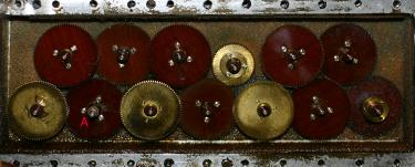
Moving on to the gearbox itself I removed the bazillion (well, 32) screws securing the back plate. That was awkward, given that the motor and the motor cover were both still tethered to the works by their cables. There was a lot of paint-like varnish around some of the screw heads, not sure what that is. Paint? Varnish? Hardened ancient oil? I had to remove the front panel in order to release the two mounting screws on the bottom of the plate. The back plate was then loose, but still held on by the drive yoke and the shafts poking through it; they didn't want to let go. The drive yoke was secured with a 5/32" Allen screw, but even with it completely removed the yoke didn't want to come off the shaft. (This is the "A" dial shaft, it goes right on through and out the front to the dial.) I had to pry from behind while carefully tapping and prying on it to get it starting to loosen up. The gears 'jammed' while trying to pull off the back plate, that actually helped in that I could then start to 'unscrew' the drive yoke. I worked it off. With that out of the way there should have been nothing holding on the plate, but it wouldn't let go of the dial shafts, especially the drive shaft. I tapped the shafts in with the handle of a small screwdriver, which got the plate looser than before, yet the drive shaft still wouldn't let go. I got a screwdriver behind the plate and bridging over the gearbox, then started tapping on the end of the drive shaft with a small hammer. It finally let go and let the back plate come completely off. (The bronze sleeve bearing actually popped out of the rear plate.) It was becoming apparent that the drive shaft bearing had been the tight one that had been causing all the trouble. The exposed fiber and brass fine-toothed gears (alternating) all turned easily and smoothly at this point. (In the picture I labeled the "A" gear [the one with the drive shaft], in red.) With everything exposed I was able to clean out all the rear bearings.
The 'paint' flakes are the remains of the back plate sealer. I'll need to find a replacement, perhaps an automotive RTV, in order to be able to properly lubricate the felt-lined gearbox. It looks like there should be enough of a 'puddle' in the bottom to throw up onto the gears when it starts up, but not so much oil that the gears stay running in it—the excess should be up on the gears and in the felt. It would be helpful for the gearbox not to leak out the bottom as it puddles for the next use!
For the record the A dial is direct drive and spins at 1650 RPM for A-440—this is the required spindle speed if making your own tuner out of disk drives or the like, and if using the same kind of pattern disk: concentric bands of 2–128 equally-spaced light/dark marks in power of two increments.
In my next session I filed the gouged drive shaft gently until it would let the bronze bushing work off the shaft, then I pressed the bushing back into its hole in the back plate.
The next day I scraped off the mating gasket surfaces with a razor blade and a pocketknife and washed them down (for the first time) with brake cleaner. They look good, ready to mate with the new automotive RTV gasket sealant I bought. I also used cyanoacrylate glue to secure the one bronze bushing that had popped out of the back plate.
My next session saw the back plate reinstalled. I cleaned off the mating surfaces and ran a thin bead of RTV gasket maker around the back plate, then I tapped it on over the drive shaft while twisting the shaft with pliers and using the locating pins to hold the plate in position. That shaft was still tight but the rest of them were no problem: they just slid right into their places, then I put in the 32 retaining screws. Once I got the plate fully seated the dials all spun easily again, even with just fingers on the bare protruding drive shaft. The motor is temporarily clamped to the back plate while the seal sets up, since some of its mounting screws go through the plate and I want the seal to be fully compressed on all sides. So far, so good! The RTV requires 24 hours to fully cure, I guess I can wait that long.
The next day I cleaned off the mating surfaces of the motor housing and reassembled the spring-drive yoke. It turns out that the Allen screw for the motor end of the yoke can be reached easily through the oil zerk hole, so I removed the drive assembly from the motor and attached it to the gearbox end with its (smaller) Allen screw. I dipped some of the 5W20 motor oil onto the gearbox shaft ends, then applied some sealant to the motor's flange and put it together loosely. I tightened the drive yoke to the motor shaft, but left the mounting screws a bit loose, per the sealant instructions. (Which I read this time.) Tomorrow I can tighten down the motor and then begin putting it all back together. The dials again spun easily from the motor's cooling fan.
The next day I put the Scanning Unit back together. (Mostly.) I got the motor and the gearbox attached to the case, and powered it up. It ran easily, but it made kind of an intermittent heavier mechanical thrumming noise. I loosened the drive yoke and re-seated it with less stretch on it, then it behaved itself. I put 15 ml of oil in the gearbox, corresponding to the manual's stated 1/2 oz. I put a shot of oil into the drive yoke, too. When the motor was driven by the Tuning Unit I had to re-set the gain due to the change in mechanical loading, but after that it worked perfectly. After work I put the amplifier back in the Scanning Unit, and connected things back up to try it out. It worked, though as I tried playing trumpet into it I found that it's a bit harder to use than I'd hoped. Still, I think I'm going to enjoy it. I still need to make/find a transposition scale knob, and to put the case covers back on. I'm using a piece of rubber vacuum tubing as a handle for right now.
Finally, reassembly day! I dug in the garage and found an old Mercedes door lock knob. Black plastic, with an aluminum trim ring, it matches fairly well stylistically and is approximately the right shape. I cut off the excess plastic from the bottom with a razor blade, which made the overall length and travel (when in place) correct. The threads inside (#6-32) were even correct, but they were too far inset into the socket. I used a piece of the old friction tape that came out of the unit to wedge inside the threaded socket, then the thing screwed onto the scale's attachment well enough to function. When pushed in as far as it would go the "C" scale is selected, which is correct. (The scale alignment is adjustable by screwing/unscrewing the knob.) As perfect as this is going to get right now! (If there's a later problem with the tape I can epoxy-fill the socket and re-drill and tap for better security.) I then attached the cover to the Scanning Unit and scraped the tape residue off of its glass face with a razor blade. When powered up it's actually pretty quiet with the cover on, I guess the felt lining helps. I then reassembled the Tuning Unit. Done?
Now that the tubes are enclosed and in the dark, so to speak, I note that there is a disturbing blue glow in one of the 6L6's of the Tuning Unit, and in one of the 6V6's of the Scanning Unit. Gassy tubes? Will have to keep an eye on this; both these tubes are on the more expensive side as they're used in tube guitar amplifiers, both vintage and new, so demand for them is high.
No. I did a bit of research on the blue glow, and according to http://www.netads.com/~meo/Guitar/Tubes/blue_glow.html it's pretty certain that the blue glow I'm seeing is fluorescence in the glass from stray electrons, and not a problem at all. Good.
I deployed the tuner in the music room for Christmas 2009. I used it numerous times thereafter, but I wasn't able to get the results from it that I'd hoped, and I ended up using the little electronic tuner as often as not. (It's possible that degraded power supply filtering is resulting in a less clean signal than it ought to have, and that might be something I try addressing later.) More to the point, Jill said quite definitively that she would never use it. So with great sadness I removed it from the music room; in spite of being tres cool it was occupying too much space for the utility we were getting from it (i.e. none), and Jill was not happy about that. It's in storage now, this is a great disappointment to me.
...I still want to use it, so later I renegotiated its location in the music room and found (I hope) a less objectionable spot for it. We'll see.
...I was doing some recording and tried a normal dynamic microphone in the tuner. It worked better! I tried the Vaco crystal microphone in the tape recorder, and it sounded nasty! The lows are cut off, which explains why I wasn't getting the octave bands on the tuner responding the way I thought. The dynamic mic is a little less sensitive, but not so much as to matter. I have switched over to the dynamic mic for now.
The total dollar investment in repairs, counting junkbox items as free, is about $15, all of which went into the test equipment! (The tube tester and the HV power supply.) Glues, oils, and solvents also not accounted for, as they're generally spread over everything I work on. Many hours were burned, however.