The magnificent Kohler genset is not really a perfect fit for our application, and its proposed replacement is as yet nothing but a gleam in my eye and a lump in the garage. We have a couple of gasoline rope-pull generators which do yeoman's work, but I really have a liking for diesel generators. They are much more fuel-efficient, and tend to last a lot longer. They're also much better at sitting unattended, diesel fuel doesn't go bad nearly as fast as gasoline does. (Nothing beats propane for sitting, however.) There's a place in our stable for a small diesel genset, even if we have a big one for high-load periods. Unfortunately they tend to be expensive.
So I was at the local discount liquidation outlet, mostly Costco returns it seems, and they had one of their diesel generators there, wheels missing, battery out/dead, etc., for $390. (This is the same place I bought a tiller that had a thrown rod, unbeknownst to me, and by accident a gasoline generator that had a thrown rod [I pointed to the wrong one]... so definitely it's a place to be careful!) I'd seen these generators there before, in presumably running condition, for about $800. The lowered price... seemed... strangely... compelling. I bought it! I later found this information on the net:
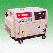
Except for the paint job, the diesel generator at Costco looks like this:I pulled the following information (and the photograph above) from the website, in case the link should disappear:But instead, the Model Number is #41450 "Matrix". The manufacturer is Jiangsu Changfa Group (China). 20" wide, 25" high, 36" long. 418 cc. Weight = 346 lbs. Colors, dark gray and light biege. 4 gallons fuel = 9 hrs under load. 5000 watts constant. $1050. Electric/battery key start. I don't think the wheels are included.
Silent Type Generator Powered by Super-Light Air-Cooled 4-Stroke
Direct Injection Diesel Engine
Model Number: CF3500LN/CF5000LN (3KW/5KW)
If this generator works out I can get rid of one of the gasoline rope-pull jobs. I'm sure I can off one on friends or neighbors.
I found that an equivalent (?) expensive gasoline 5 kW generator (that Costco has right now) is rated to run for that same 9 hours, but on a 6.5 gallon tank. So the diesel is automatically 50% more efficient, right? And at partial loads it should be even better than the gasoline models.
Unless the motor is dead.
Once it had run a few times it started easily with the key. I'm sure being warm helped, as did getting all the air purged from the fuel system. The set takes a long time to spin down when turned off. There's a spring-loaded red lever behind the access hatch that applies throttle. If you hit the red-handled release lever it drops to, or below, idle and stops. There is also a red lever on top that I don't know the purpose of. It can only be accessed with the enclosure's end cover taken off.
There is no voltage output, either AC or DC. I checked the wiring and such inside the cabinet, and there were no obvious faults or burned items. The regulator is potted, so that's not very handy. There is an exposed power diode bridge, but it checks out OK. There are no specs or schematics that I can find, I'm not sure where to look next. There's an odd heat-sinked box separate from the regulator that hooks to a pair of green wires that come out of the flywheel area. Low-oil shutdown? Overspeed protection? It has an inline fuse hooked to it, which I checked. Also good. There are a lot of wires. There is a knot of three automotive relays tie-wrapped behind the control panel. Not too elegant. They're involved with the shutoff solenoid, at least. (I haven't delved into it thoroughly.)
It's a mystery. Perhaps I've just purchased a one-lung diesel motor for $400? Still not a bad deal!
When I took the big car battery off I found that the little one (36 Ah) was now taking a charge. We'll see if it recovers enough to be usable. It, not fully charged, wasn't (yet) able to fight the engine's compression enough to turn over.
...Somebody suggested the mystery red lever is a compression release. OK, but you can't operate it normally as it's hidden inside the enclosure! I tried starting it on just the little battery and it fired right up. But it's warm outside now. The battery was still drawing 4 A several hours later. It may be bad... Some hours later it was down to 2.5 A, that's a good sign.
I had a couple of small ball-bearing hub wheels lying around that actually fit on the axles, though they're large enough that they rub on the case some. They'll help with the moving around, methinks.
The red lever on top is a compression release, obviously not intended for operation in this particular installation. I pulled some tie-wrapped wiring harnesses and connectors open, one two-wire connector with red and white wires towards the generator end that had a plus label on the red wire measured low ohms, but generated no voltage. Field winding? The two green wires from the flywheel end measured low ohms, and generated 44 VAC when running. As I mentioned before, they go to a four-terminal epoxy-potted heat-sinked dingus, labeled KDK-12, by the Huifeng Electrical Machine (Changzhou) Co. Ltd. It has a fused red wire coming out of it, and the case is grounded. It has a date code of 2004.03.15 on it. I was unable to find anything on the internet. Perhaps it's a 12 V rectifier/regulator? I put it on the bench and yes, it is. Fed a variable AC voltage, the DC output comes up with it until it hits about 14.5 volts, then stabilizes. Cool. It has a 10 A fuse. (The 8 A 12 V output on the front panel comes from a separate winding on the generator end, run through that big heat-sinked bridge rectifier. It doesn't look like that circuit is shared with anything else.) When I fired up the generator again the battery voltage measured 13 V, when I connected the regulator's output the voltage started rising. It's charging, anyway. (The regulator obviously doesn't have a feedback mechanism into its generator; it probably has to burn the excess energy, making the heat sink particularly important.)
The small-gauge two-wire (red and white, red collared with a "+" label on the potted regulator side) connector to the generator end measures 17 Ω. I fed it battery power through a test light but the generator didn't generate, at least according to the incandescent lamp I had plugged into it. (Yes, the breaker was on and had continuity.) The other connector between the regulator and the generator has four mid-gauge wires, two blue and two yellow. One set, yellow, measures 0.1 Ω, the other, blue, 0.5 Ω. All of these three windings (?) appear isolated from each other. I need to figure out which of these, if any, is the field. Could there be more than one? There is another connector from the front panel that has four wires, red, black, and two white, I assume that's the power and control feed to the regulator. When running there is power between each of the other three wires and the black wire. The main generator output is large-gauge wire, and goes to a terminal block. No mystery there.
The potted regulator is in two pieces, and there are two trim pots sticking out. The tops of several standard-looking components are sticking up out of the sea of epoxy. I sure wish that was a serviceable item!
I e-mailed a request for information to the contact listed on the web site, cfpmc@public.cz.js.cn, and it bounced almost immediately:
Mailbox space not enough (space limit is 9000KB). Size of arriving mail (1KB) exceeds free space (0KB).
On the plus side the battery had stopped taking a charge, and though it was a cool morning it fired right up. I did use the compression release this time. I reinstalled the battery into its place.
Dare I use the phone number "For Information or Service" on the front? 1-888-896-6881, could it be as simple as that? This got me All-Power America, but its hours are M–F 7–4 Pacific Time. I'll have to try again tomorrow.
...I stopped by Harbor Freight and bought four solid casters, on sale for $3.50 each, to try to use as wheels. They come apart easily enough, but would they fit? The axle holes turned out to be a bit small, so I pushed the axle races out and drilled them out to 1/2". Then the wheels went on the axles easily. Bent nails through the cotter pin holes hold them on. They do tend to come partially apart because the brackets that used to hold them together are no longer there, I may have to do more later. It was good enough, however, to allow us to roll it down the ramp out of the truck. I put it in the garage. (No small feat, it's pretty full in there!) The generator is much easier to handle with wheels on it.
Somebody (thanks Scott!) sent me a link to a manual for a different generator. Not too applicable, but it appears to have the same motor (Yanmar L100?), and has some general information about generators. Wrong number of windings and type of regulator, however. Mine is obviously much more elaborate. If mine is indeed brushless as the poop sheet claims, there are diodes on the rotor that should be checked out. He also sent me a link to another, much bigger, generator that actually seems to share the exciter configuration of mine, though mine is only single-phase. This configuration has two output windings that can be connected series or parallel depending on the needs of the regulator itself, which drives the exciter's stator winding.
If this is my generator's configuration, I've already fed power to the exciter's stator winding to no effect. In which case something that spins is dead. Perhaps the rotating diodes have a problem? Let's hope so!
With the end panel removed it was also obvious that the battery is installed wrong way around. The retention strap is not centered, and is wanting to pull into the terminals. I'll try turning it around so the terminals are on the side opposite to the retention strap, but if I recall correctly the positive cable is a bit short to reach. We'll see.
When I tried the service phone number it was busy. Figures.
I tried again a little later and got through. They said that parts and service information are available, and they're sending me a parts breakdown and owner's manual. I told them I probably needed a brush pack, and they'll look it up and call back with pricing.
I checked their web site, and found what looks to be nearly the same generator. Here is what they list:
| Part # | APG3202 |
| Power | 6500 W |
| Weight | 377 lbs |
| Parts List | Not Available |
| Specs | Not Available |
| Manual | Not Available |
A lister said:
That is great news. The brushless gen heads I've seen have all been low-end. The ones with brushes last forever—as long as you replace the brushes as needed. If you are lucky, there are oil ports on the bearings. Chances are you can match up the bearings with something from Timken if and when you need to. The Chinese ST generator heads have been known to last for decades of constant use with little maintenance.Of course, I don't know if this is any kind of an 'ST' head, what I know of those they're all heavy-duty 1800 RPM jobs. My best guess is that it is not an ST head.
The field winding, interestingly enough, measures some resistance to frame ground from each terminal, it is not isolated. It might be shorted to the armature roughly halfway in the middle of its 17 Ω. I'm thinking that's not a good sign.
Disgusted, I did manage to turn the battery around. The positive cable is definitely too short, but I managed to make it reach anyway. The motor, without its mufflers, is quite loud.
I found a link referring to troubleshooting basic generators. Herein is the information, paraphrased and tidied up, for link failure insurance:
These comments are are about all Chinese ST heads.
The first step in trouble shooting is to assume nothing. Verify that your head is indeed wired as above. If you find it is wired different, you might consider making a note of how it is wired now and then wire it as above for the purpose of testing. Note: if you have a center tapped head, it will be just like the drawing above.
There is a piece of test equipment called a 'megger' that's nice to have for testing electrical appliances. The one I had experience with in the Navy had a hand crank, you'd hook it to the windings and then to the case or the ground terminal on a gen set and crank it up. This performed a high voltage test between the windings and ground. If the insulation was failing or breaking down, you'd see it. If you can get your hands on such a tester, do so. If not, use the good ol' multimeter like most of us, and proceed.
Use these test procedures at your own risk, this information is for educational purposes only! We'll assume your generator head is dry and clean and that you have grounded the head to earth ground to protect yourself. We'll also assume that it's hooked to the engine and that you can spin it up to 1800 RPM's. We also must assume that you have a good idea where 1800 RPM's is, or that you have a device like a mechanical tachometer to verify that the speed is correct. (That's a lot of assumptions!) If all this is true, proceed to Step One. Remember! the following readings were taken off the 10 kW head.
- Remove the slip ring cover and lift both sets of brushes off the slip rings. A little messing around and you'll see they stay up on their own when lifted up far enough. Make a tool out of a paper clip to pull the spring back over the top of the brush when you wish to seat them again.
Place your ohm meter across the slip rings and take a reading on the R×1 scale, you should see around 17 Ω. If true, go to Step Two. If you find a different resistance the field is suspect, consider pulling the rotor. You'll find four windings in series, inspect the solder joints and connections to the slip rings. Open the individual windings and compare them using the ohm meter. Check the field to the shaft, you should read infinite (open circuit). Once you have corrected problems here or have proven it good, go to Step Two.
- Place the meter on the R×1 scale, and place it across the field supply leads when they are removed from the diode bridge. The reading should be around 5 Ω, if true go to Step Three. If not, investigate the harmonic winding (field supply) in the stator, and replace it if bad.
- Connect the volt meter across the field supply leads. Set the meter for AC volts, 100 volt scale. Start the engine and bring the set to 1800 RPM's. You should read approx 53 volts AC, if true go to Step Four. If your reading was different, verify you are turning 1800 RPM's, if true, investigate. Stop the unit, take a 12 volt battery and 'flash' the field with the brushes lifted on one ring, put the brushes back on the rings and repeat Step Three.
- With the set stopped, reconnect the field supply leads to the diode bridge. Start the engine and verify the set is running at 1800 RPM's, connect your meter to the two screws that normally connect the two leads going to the slip rings, and note the DC voltage. It should be around 69 volts DC. If this reading is good go to Step Five. If it is off, replace the diode bridge and retest.
- If you got this far you've proved you have a correct voltage from the field supply winding, that it is being converted to DC by the diode bridge, and that you have a proper resistance in the field winding. If you have an ammeter that can accurately measure 2 amps AC place the meter in series between the field supply winding and the diode bridge terminal screw. Check all the brushes, slip rings, and connections. Start the set and run it up to 1800 RPM's. The meter should read approx 2.1 amps, if true go to Step Six. If your reading was different, verify your meter, the RPM's, and the field excitation circuit, also look at the diode bridge for a flaw. Test the diodes with the multimeter to prove them good.
- You've proved that everything is working on the excitation side. The only thing left is the output side. Continue to Step Seven.
- Verify that all test leads are removed and all the leads in the field excitation circuit are tight. Set the ohm meter on the R×1 scale, place one test lead across the output winding terminals, you should see a very low resistance, 0.02 through 0.06 Ω. If not, verify that the split windings are strapped correctly. Using the ohm meter measure between the winding and ground, the reading should be infinite. If true go to Step Eight. If there is any reading other than infinite (open) to ground, look at both windings further. Replace if necessary.
NOTE: It doesn't matter which slip ring the plus and minus sides of the rectifier are connected to, as long as you flash it in the same direction. Use a 12 volt battery, and 'flash' the field according to the plus and minus markings of the rectifier. The smart DIYer will make one of the brush rigs with a plus for quick reference later. If you take things apart and swap the leads, you will need to flash the field accordingly! Some have found the outputs of the rectifier are reversed from the drawing provided with their generator. This is not a problem as long as you note the polarity before you attempt to flash, and as long as you know that swapping these leads will kill the excitation voltage 'til you flash again correctly!
- Place your voltmeter across the output winding leads, set on a scale to read 230 volts AC. Start the engine and set at 1800 RPM's, if your reading is not close to 230 volts AC you most likely have a problem with your RPM's, your meter, or your output windings or associated leads. Get a megger and test all the windings with it. If you got here and didn't clear your problem, you are one unlucky person.
Please report any errors or omissions you might find in this text.
05/2006 Note: To date, the leading troubles in the ST design are noisy bearings and rectifier failures. The old Chinese-designed rectifier appears to be a variation of the first generation solid state rectifiers that immediately followed the ancient and bulky selenium design. This first generation unit is air cooled, made of too many parts screwed together, and is far too prone to failure. Utterpower is consulting on this, and hopefully PS heads will have better rectifiers as stock. Until then there is a retrofit kit called the ST-Mod kit that eliminates the doghouse all together and provides a far better rectifier.
As for bearings, leading causes of bearing failures are the assembler using cheap bearings, attempting to ship the bearings with little or no grease, or packing them in Yak fat instead of a proper grease. There are other problems, some assemblers will cheat the importer out of a shielded bearing on the fan side. This means the bearing and grease is open to pick up all the grit and dirt blown into it by the fan and soon you'll have a grinding compound in there working to take out that bearing in record time.
Regardless of what the importer ordered, you will only know it's right if you check. Don't have time to check? Get something else.
I was nearby so I swung by the discount store again, and the other generator was gone. Sold, I imagine. I doubt there was anything I could have learned from it in practice, and I certainly wasn't going to get another one, especially at 'full price'!
I also found a link to a forum entry on the theory of this low-cost regulation system. Interesting reading. Here is the most interesting information in case the link dies:
I have a diesel-driven 2-pole alternator (single-phase 230 Volt 50 Hz running at 3000 RPM. It is brushlesss and has a capacitor across the windings. What is this cap for?Interesting reading. The upshot is that the cheap resonant regulator seems to operate, similar to a constant-voltage transformer, by running in saturation and burning excess mechanical energy as heat. I would expect them to be markedly less efficient at partial load as a result.It provides the excitation and sets the frequency.
The capacitor plus the inductance of the winding form a "tank circuit"—a resonant circuit that "rings" at a particular frequency.
What happens next depends on the type of rotor you have in the alternator. (I'll describe it as if it were a squirrel cage, then delta the description for a wound-coil-diode variant.)
The ringing coil/capacitor combination produces an alternating magnetic field. If the rotor is turning at roughly the frequency of the ringing, the magnetic field from the ringing current will try to magnetize the rotor with a pair of poles. If the motor is trying to push the rotor faster than the speed that would exactly match the ringing, the rotating magnetized rotor will push against the field (which will resist it) and pump energy into the ringing (which will make it stronger).
Meanwhile, the slippage between the slightly-faster rotor and the field from the ringing coil "drags" the magnetization through the rotor. This induces a (large) current in the squirrel-cage conductors. This current maintains the field and resists its motion through the rotor.
Once started up (by a trace of residual magnetization in the rotor and its motion at or above the critical rate), the ringing and magnetization build up in an avalanche until they are limited by the "saturation" of the magnetic core material of the rotor and/or the stator. (This provides the voltage regulation.) After that point the rotation maintains the magnetization in the rotor and the ringing coil, pumping energy from the motor (by drag on the shaft) into the currents in the tank circuit and the squirrel cage to replace the energy lost to resistive heating.
With the rotor magnetized the correct amount and rotating at the correct speed, its magnetic field also generates a voltage in the output winding. Current can be pulled from there, and when it is the current resists the motion of the rotor—forcing the motor to provide the energy that drives the current into the load.
If the load pulls two much current, one of two things will happen: The rotor will slow down below the critical rotation rate to keep the tank pumped, and/or the load will start reducing the magnetic field of the rotor. Pull too much current and energy isn't pumped into the tank fast enough to replace what is lost to resistance. The ringing collapses, the rotor's magnetic field collapses, and the output voltage drops to almost zero. (This limits the output current.) Reduce the load sufficiently and the ringing will build up again.
Turning off the motor while the load is still attached MAY completely demagnitize the rotor as the generator slows down. Then you have nothing to get the process restarted again the next time you start up. You can restart things by "flashing" the rotor—driving a current through the output windings by connecting one wire to one side of a battery and striking the other wire against the other battery post. This may work if you do it when the genny is stopped (creating some residual magnetization in the rotor), and it WILL work if you do it while the motor is running (getting current going in the rotor and starting the ringing-pumping before it collapses). But use care if flashing when the motor is running, because the generator will go to full output in a fraction of a second, leaving you holding hot wires and/or with the hot wires stuck to the battery.
Squirrel cage rotors work. But they have problems. The big one is that they are lossier than they need to be (due to the slippage of the mag field through them). Another rotor type has a coil of wire to create a magnetic pole pair at a particular place in the rotor, with a diode across the end of the coil. The diode rectifies energy from harmonics and off-speed motion to get a pole started at a particular place. Then the shape of the pole pieces combined with the current keep it pinned there, without slippage, as the ringing builds its strength. Absent the slippage the excitation circuit only steals enough power to keep its coil ringing—you lose the losses that would otherwise drive the currents in the squirrel cage.
Is it [the cap] like a motor which has a cap for a start winding or aux winding?
No. In a capacitor-start or capacitor-run the capacitor is connected in series with the coil and the series pair is hung across the input power, along with the run winding.
The capacitor causes the current in the aux winding to "lead" the current in the run winding. (Ideally, it's a quarter-cycle early.) With only the run winding operating you get an alternating magnetic field. With the run and aux windings operating, you get two out-of-phase alternating fields at different angles, which amounts to a rotating field.
When the motor is stalled, a one-coil alternating field doesn't really give it a push in either direction. It will tend to sit there and buzz. Once it's spinning the rotor will be in the right position to be pulled toward the pole pieces during the high part of a cycle—but as it arrives the half-cycle is ending, and once it passes the next half-cycle builds up a field which again pulls it along. So a rotating motor will keep rotating, pretty efficiently, unless you drag it to a stop.
A capacitor-start motor only operates the aux field during motor start. A capacitor-run keeps it operating (typically at a lower strength than with a cap-start) even while the motor is running. This gives the motor a stronger and smoother pull, since it gets a strong pull at all parts of the cycle, rather than only during two of the four quarter-cycles.
The genset is rated at 2.7kVA has no engine governor as such
Fine control is not needed because once the rotation rate reaches the correct value for the resonant circuit the alternator starts resisting further speedup.
But you may find some throttle control to make the motor drive harder when the load becomes large.
The sine wave on the scope looks a bit peaky not as nice as off main grid
Probably due to the saturation of the core material.
Is there any thing I can do to give a better wave form so that the eletronics in my inverter will see it and turn battery charger on?
You can hang a capacitor across the output. (Just don't make it large enough for the OUTPUT coil to resonate at a lower frequency than the excitation coil, or your output coil will start acting as an exciter and the generator will start running at a lower frequency.)
I doubt that there is much you can do to improve the waveform, it is generally poor with that type of alternator. Anything relying on iron saturation usually has a high in-phase 3rd harmonic (peaky waveform). It should not be bad enough to confuse your battery charger.
It may be confused by the volts or frequency being out of limit. With these cheap alternators the volts are proportional to speed and if the speed is high the volts may be out of spec for the charger.
Many of these chargers are too clever to work from poor quality power sources. Also, the high reactance of many small alternators will make battery chargers perform badly (the peak of the waveform is lopped off and that is where most chargers extract their energy)
You may find it will work with a significant resistive load on the alternator such as a halogen spotlight but it will not help the fuel economy.
Yes a capacitive load causes a rise in alternator volts. With enough capacitance it will self excite.
Even well-designed alternators with AVR control of the field will lose control if too much capacitance is added. These things are generally designed for 0.8 of lagging, you never see ratings quoted for leading power factor.
And here is an interesting white paper (master's thesis) on generator voltage regulator theory. Extracts:
The auxiliary winding is designed to utilize the air-gap flux-density harmonics to supply the excitation power to the automatic voltage regulator. The auxiliary winding is wound into the stator slots together with the main winding. It is located on the top of the slot near the air gap.In this I find the first plausible explanation of why my generator might have what appears to be two separate excitation windings. One winding reacts to no-load conditions, and the other to short-circuit conditions. One is at the fundamental frequency, and the other is at the third harmonic. Together they span the range of loads from zero to shorted, and give a first-order response for regulation. In other words, the electronics of the regulator itself can be simplified if they're powered from the series combination of these two windings. If this is indeed what I have, my generator is considerably better than the run of the mill.In no-load operation, the terminal voltage of the generator is induced by an almost purely sinusoidal flux time harmonic. Clearly, this fundamental can also be utilized to obtain the excitation power in no-load operation. As the load increases, the armature current and the saturation of the machine cause higher order harmonics to arise and also these harmonics can be used in excitation. In generator short circuit, the flux is highly distorted and contains a relatively high third harmonic component which should be utilized to provide the excitation power needed in short circuit.
The auxiliary winding must be designed to utilize the chosen flux-density harmonics in different situations. The coil pitch factor determines the voltage induced by a certain flux-density harmonic. For the auxiliary winding solution to remain as simple as possible, only the minimum number of harmonics needed should be utilized. As mentioned, utilizing the fundamental and the third harmonic should be enough in no-load, load and shortcircuit operation.
For low-voltage synchronous generators, only the lowest order harmonics are to be utilized to obtain the excitation power. For the solution to remain as simple as possible, only a single-phase auxiliary winding will be used. In the following, three different winding constructions are studied considering the low-voltage synchronous generator excitation. Construction 1 presents an existing auxiliary winding solution utilized in some smaller sized synchronous generators. It only utilizes the third flux-density harmonic for excitation. In Construction 2, an attempt is made to study the principles of utilization of both the flux fundamental and the third harmonic in excitation. Being slightly different from Construction 2, Construction 3 also utilizes the fundamental and the third harmonic and guarantees better results considering the excitation also in generator short circuit.
...
Construction 3: Separate windings for the fundamental and the third harmonic. Winding H3 alone can be designed for the short-circuit excitation and the voltage in no-load and load operation can be adjusted by adding coils H1 in series without the fear of too high excitation in generator short circuit.
Depending on the voltage induced into H3 in no-load and load operation, H1 can be installed in different ways to adjust the voltage induced into the auxiliary winding. If the voltage is too low for overload excitation, H1 is wound in the same phase as H3. However, in case the voltage is too high to supply the automatic voltage regulator, it can be lowered by installing H1 so that a phase shift of 180° occurs between the voltages induced into the windings. Clearly, if H3 by itself is applicable to supply the voltage regulator in every operating state, H1 is not needed and the solution remains simpler.
Except, of course, that it is broken.
Regardless of its design sophistication, its construction seems no better than any other cheapie. And don't get me started on epoxy-potting electronics!
Anyway, all this suggests an experiment to find out if this regulation system is what I have. Procedure:
I'll need to test these hypotheses. First I suppose I should unhook the field and replace it with a dummy load, then see if it ever gets any power. If it does I could mimic what the regulator's supplying using an isolated DC source to see if it generates then.
In a way that would be nice if it did. Fix the short and fix the whole thing. But how hard would it be to fix the short, hmm? A lot easier just to blame the regulator. Easy to swap out, but not so easy to find another one.
I re-measured the field, and it's actually about 15 Ω. The short to frame is not in the middle, measurements show about a 10 Ω/5 Ω split.
I put a dummy 15 Ω load on the field output of the regulator and fired it up (the engine started instantly, even though it was quite cool this morning) using the battery charger to power the field. Loaded, and warmed up for a bit, the output of the regulator was about 15 V, which was more than I was putting into the field. (For whatever reason, the battery charger was only making 10.7 V into the field.) The regulator was pumping out more voltage, that should initiate the positive feedback required to bring the output voltage up to normal.
I checked, and the blue and yellow excitation windings are not directly hooked together. One side has megohms of resistance, the other is open. When running, one winding was putting out about 8 V, the other 4 V. A rather interesting fact is that the frequency output of both was the same according to the Fluke, which I guess isn't surprising because there shouldn't have been any third-harmonic saturation yet, and the frequency was exactly 60 Hz. (I could fiddle with the engine's speed governor and affect this.) When I hooked a 100 Ω resistor between the dummy-loaded field output of the regulator and frame ground there was no change in its output. It's not appearing that it will particularly notice the field short.
I was tricked by the Fluke, I initially thought it read 50 Hz. It's been getting worse the last couple of years, display segments have been fading out. (And unlike my usual fare, this is a unit that I bought brand new, retail.) I went to adjust the motor speed and found that it jumped to 59 Hz from '50' when I poked it. There were just too many missing segments to rely on this thing anymore. (Is that a 2 or a 3?, a 5 or a 6, etc.) Finally I'd had enough and I opened it. Fluke 83, made in USA. Far from new anymore. It is actually very easy to open up, it's very serviceable. I pulled the LCD panel off, which is held on nicely with a well-designed plastic snap clip. I cleaned the iffy-looking PCB contacts where they join the flexible foam interconnect, then put it back together. It worked perfectly again! I was on a roll so I put Goo Gone on the plastic face and used a razor blade to gently take off the green spray paint spots that had gotten on there when I was working on the big Kohler. I then used plastic polish to restore the face to a nice clarity. It's like new again, I should have done this two years ago!
To up the field voltage I hooked a 12 V battery in series with the charger, giving it about 22 VDC input. The (loaded) regulator was then putting out about 50 VDC, the main generator output got to about 95 VAC. It's starting to look like the regulator is just incapable of putting out enough field current to do the job. I wonder what a new one costs? Un-potting the existing one to repair it promises to be extremely troublesome.
I cut the last wire ties apart in the control panel, I need to trace the wiring that goes to the regulator to see what it really does.
The other unit hooks to the front panel and has a current transformer looped around the main output that it connects to. Constructed like the regulator, it has GTDK date codes of 7/06, or perhaps 1/01. Stamped on the side is "BI-1 06.07", or perhaps "B1-1". Protruding through the potting is a relay, an LED, and a ten-turn trim pot. Two small electrolytics lie just below the surface of the potting. This looks to be an overload shutdown or something like that. The potting had pulled away from the shell, the block was easily removed. The back (PCB) side was crazed, this potting material looks brittle enough that it may be possible to remove it easily. Cold (dry ice?) may be of great help.
I pulled the regulator out of its shell, but I was too energetic and managed to crack the shell. (No great loss.) There were voids in the potting, part of the PCB was exposed. There was a great deal of a coarse white granular material mixed in the black potting at the 'bottom', I don't know if this is un-melted potting material or a component thereof, or what. But this potting looks very brittle (especially where the granules are), I may be able to expose the circuitry with some care. I have this idea to use dry ice to get it very cold and brittle, and chip it off. Maybe use heat stress alternating dry ice and the heat gun. I just need to be careful not to freeze the electrolytic capacitors and ruin them!
That'd sure do it! I'll need to figure out why it blew, however. The potting material is somewhat brittle and can probably be chipped away with patience. Even without exposing the component side I should be able to do at least some circuit tracing.
...After work I stopped off and bought some dry ice. I put it in a bowl with some acetone to make a cold bath, and dipped various corners of the potted mess. I was then able to chip off chunks of it. In one session I managed to expose enough of most of the componentry to start tracing the circuit out. I did manage to break several components, that is unfortunate. They can, I hope, be replaced. In addition to the three protruding power transistors there are two signal transistors, at least a dozen diodes, and several power resistors. And the usual small handful of resistors and capacitors. The blue excitation winding feeds a heavy diode bridge, the yellow feeds a light diode bridge. Blue obviously powers the unit, yellow is apparently control. (Third-harmonic winding?)
The coarse white granules in the potting appear to be ceramic, like porcelain. Filler? Floor sweepings? Low-grade nuclear waste? Wherever its concentration was the highest was also the easiest pickin's.
Some testing showed that the small bridge's diodes are all shorted. There is a MOV across the output, and it is shorted too. It was probably the original failure, which cascaded and took out the diodes and then the trace. This is bad design, MOV's usually fail shorted, with wear, and to put one in a circuit where it can't be replaced and where there's no fuse to handle its eventual failure is just foolish.
The regulator's major mode of operation seems to be using shunt resistors to burn the excess field power.
With care and a jackknife I have been digging in what potting is left. I've exposed another two resistors and a glass-encapsulated diode. (Or perhaps a capacitor, I've seen those that look like this but I suspect a signal diode. The Fluke indicated open-circuit both ways, but I didn't try too hard. Capacitor? Burned-out diode?) I've also managed to cut a signal transistor's leg. The two signal transistors are "S8050". (Also marked "D 331".) There's still a component or two lurking in there. My best bet may be to desolder and remove selected components, especially the electrolytic capacitors, in order to gain access to more potting material to dig out. Then I have to finish tracing the schematic and come up with values for the various components. Big job!
I saw an ad on Craig's List for a substantially similar generator, brand new, but with a few more bolt-on features like a small transfer switch and a few more watts. $1900!
Because it was easy to do I popped the potting off the bottom of the other (overload?) board. It's got a 14-pin IC on it. I'm not going to try to unpot the components. It's probably not broken, nor is it critical to generation. Maybe later, if it gives me trouble.
The iron had warmed up while I did the overload board's trace-side potting removal, so I then removed the regulator's two electrolytic capacitors and the large bipolar transistor. These exposed the MOV component label (it's an 82 V unit) and the remaining potting blocks. I surfed for the big transistor, and found that there is a Chinese T2142 "Dynamo Transistor", whatever that is. No other information on it, yet. The multimeter indicates that it's more complicated than a basic transistor. I exposed the components over by the trim pot, and found what I expected. Unfortunately I cracked the glass diode! Probably no way to tell what it was now. Zener? 1N914? Capacitor, even? I pulled one of the green-dipped mylar capacitors and measured .0012 nF on the bridge. That's down in the noise. I exposed the parts under the other potting blob and found another transistor! OK, that explains the pin count. Marked "A42" and "B331". MPS-A42? That's a high-voltage level translator, rather old in fact. The PCB hole pattern was not customary, but so what. The remaining component was a resistor, as expected. The big transistors were labeled MJ10012, which is not a FET at all! They're power darlingtons, with clamping diode. (Last I was taught, it's not too kosher to parallel BJT's without small emitter degradation resistors. That's one of the reasons I assumed they were FET's.) If these are BJT's, they may be dead. I measure a dead short between C and E. This board is starting to appear to have been thoroughly fried, and half of what didn't suicide has now been killed by me. <Sigh.> Well, it didn't work before I started messing with it, either!
Anyway, so far the schematic I have prepared contains only the layout and the parts list. While I have a penciled schematic, I must rearrange it a few times to put it into intelligible form. There's an art to good schematic design, after all...and I'm no artist.
The mailing list guys came through, and found me a datasheet for the T2142. It is, in spite of my later fears, pretty much what I had originally figured it to be. So the circuit is still a mystery. (The T2142 may in fact be a decent replacement for the dead transistor in the 380 SL's original ignition box.)
...In the evening I did some more circuit sketches on paper, and finally got a topography that is not so confusing. One of the characteristics of a good schematic is that the 'important' circuit paths, in this case heavy current flow, are direct and straight-line. Another is that circuit components are positioned vertically roughly according to their relative DC voltages. All with a left-to-right signal flow and the use of common circuit idioms. Not an easy balancing act! I think I made about six trial layouts before hitting on one that actually made some sense and could be whipped into shape. Now I just have to put it into Illustrator.
I got some feedback from the mailing list. Craig McCluskey writes:
It seems close to the right idea overall, but has a number of quirks:He also states that the layout of the schematic is reasonable and needs no changes.It's strange that they take all the trouble to make sure Q6 gets turned off well (with Q5 AND D11), but have not provided anything to turn Q1 and Q2 off.
D10 is in a wierd location, too, since there's no way for current to flow that way.
The current in the red-green winding will always flow from red to green (unless there's induction from somewhere else), so Q6 is the wrong polarity to dump its current. Q6 will only add to the current flowing through D11.
If Q3 is turned on, Q4 (and thus Q1 and Q2) will be off and Q5 will be off. R11 will reverse bias D11 and turn Q6 on, but if current has been flowing in red-green, now having nowhere to go, it will flip the polarity on red-green so that green is positive and red is negative. This will forward bias the body diode of Q6, which will clamp the green wire at 0.7 V above the potential of C2. But why a transistor for Q6? Strange.
D12 is the correct polarity to protect Q5 from polarity reversals of the red-green winding, and D13 will clamp the base of Q6 close to the positive rail, with the current first flowing through D11 in those instances, but why go to all that bother?
Also, C4 and R6 provide POSITIVE feedback for Q3, Q4, Q1, and Q2, not negative. Is this thing supposed to oscillate and D9, et al., provide pulse-width oscillation?
On the other hand, if the red-green winding has current induced in it, so that it's a current source rather than a current sink, and has current flowing from green to red, then the polarity of D10 and Q6 make sense. But here it would be powering the circuit instead of the blue winding, the upper bridge, and C2. And when Q6 turns on, it would be shorting the output of the red-green winding (which appears to be not a good thing). Also, if D10 is conducting, D11 will be reverse biased and turning Q1 and Q2 on only pulls down on the base of Q6, and they don't need two darlingtons to do that.
Strange.
Later another friend stated that C4 and R6 are there to eliminate the possibility of high-frequency oscillation of the field. (The field's own inductance will resist low-frequency effects.) He goes on:
C3 slows down the switching speed of Q3, just like in the voltage-amplifier section of a typical amplifier. When Q1 and Q2 are on, the snubber (C4–Q6) is seen as an RC to ground from Q3's base. This slows the transient that turns on Q3. Same thing in the opposite direction when Q3 turns off.The phase shift through C4 and adjacent on C3 is 0 at frequencies below the respective time constants. It climbs to 90° as the frequency rises, but that frequency can't be achieved from the primary effects of the slowing of switching speed.
This is basically the same analysis as an op-amp with a series RC for negative feedback, using the – as input and the + as ref. The actual low-pass cutoff will depend on the RC and the series resistance from signal to – of the amp.
This isn't like a switching power supply where you have to trade the cost of the switching speed with noise and the inefficiency of spending time in the linear region. The switching speed is a tiny fraction of the on or off time in the case of a generator.
If D9 was a forward-biased signal diode R3 must have approximately 0.5 mA through it before Q3 can start conducting, that would pin D9's anode voltage (the cathode in the schematic) at around 1 V when regulation began. R4/R1's current would be approximately 0.7 mA, so R5's current would be 1.2 mA. That would make the voltage on C1 approximately 1.5 V, which seems too low.
From this I conclude that D9 is a Zener diode, of less than 12V in value. Zener diodes start at around 1.8 V in value, but I think I'll first try something like a 6 V rating. The 1N6309–20 diodes are glass, at 2.4–6.8 V in rating. 1N6319 is a 6.2 V glass Zener. 1N746A–59A are glass, at 3.3–12V in rating. 1N753A is also a 6.2 V glass Zener. There are plenty of candidates to try.
I pulled Q1 and Q2 off the board, one was shorted C-E, the other appears OK. I pulled R1 and it's a 2k trim pot, set almost exactly in the middle. The resistors, at least, seem to be marked with their values on the board's silk screen. The potting will probably make most of these illegible. Q1 and Q2 had their emitters labeled "E".
I wonder what the original failure really was? If the imbalance of Q1/Q2, due to the lack of emitter resistors, caused Q1 (let's say) to get too hot in a positive feedback cycle instead of sharing the load with Q2 and then short out, regulation would have stopped. There would be full field applied, and the generator would have gone over-voltage. This could have caused the feedback winding to over-voltage the MOV, shorting it and then burning out the diode bridge and finally the board trace. But what, then, stopped generation? There is no doubt that the thing wasn't generating anymore when I got it. D11 seems OK, there's nothing else there to block field current. Even if Q6 were shorted (which it isn't) R9 could only cut back the field current, not eliminate it. The brushes? Yes, they were low, but how could the brushes wear out if the thing wasn't generating? Who'd run it that long? They weren't burned out or anything like that.
It's a mystery!
Another source, the 1953 Applied Practical Electricty, Volume 4 (Alternating current), by Coyne, on page 105 says:
"If the flux of the alternator field were allowed to collapse suddenly by completely opening the [field] circuit, the induced voltage might be sufficiently high to puncture the insulation of the field windings and cause short-circuits or grounds between the winding and the core."This is where it talks about making sure there is always a load resistor on the field winding, to absorb this energy before the voltage could rise to problematic levels. This circuit had enough protective diodes in place, still intact, that it should have prevented any such disaster. (The whole Q6 circuit looks like it might be designed as a snubber for this particular condition.) However, the field is shorted to the frame somewhere in the middle. If the worn brushes opened up while being heavily driven this could perhaps have caused this. OTOH, I'd expect the voltage to jump the brush gap rather than punch through the insulation, so this isn't a very good theory as to the cause of the field short.
More from Craig:
What is the power rating of R2? 30 mA through 2 k is 1.8 watts. Likewise, what is the rating of R1?I put C2 on the capacitor tester and it checks out OK. Not shorted, holds voltage, low power factor, good capacitance value.What if the MOV is intended only to clip transients and spikes? The time constant of R2 and C1 is 0.44 s, which is a long time for transients and spikes. It also gives a pole at 0.36 Hz for the feedback loop (with the yellow winding is the feedback sense winding).
If D9 was a forward-biased signal diode...which seems too low.
Not to mention that the temperature coefficient of a signal diode would make for lousy regulation.
Note also that the R1 + R4 combination can vary 3:1 in resistance, a rather wide range for adjustment.
[More than that, as R1 is actually a 2k unit.]
There are plenty of candidates to try.
Indeed there are. 6.2 V is a good starting place and is near the zero temperature coefficient point of the series of diodes.
I still wonder about Q6 and D11. If you're conducting through D11, Q6 has to be off. If Q6 is on, D11 cannot be conducting. In this case the stored energy in the red-green winding has to forward-bias the body diode of Q6.
BTW, do Q1 and Q2 have any heat sinking? I certainly hope so, particularly if they're run in the linear region.
The carburetor float in the little 1600 W Coleman had stuck and the thing flooded. (Good thing my boss didn't take me up on my loan offer during last winter's power outage!) I had to remove the carburetor bowl and clean off a little bit of varnish that'd built up on the hinge. After I put it back together it ran again without vomiting fuel all over the place. It still had an oscillating governor, which I've tamed in the past by putting on the choke a bit, so I opened up the needle valve a half turn or so to richen the mixture and dampen the oscillation. All three generators then ran fine at that point, so I turned off their fuel cocks and let them run dry. Ready for winter, I guess.
What I really need to do is get that voltage regulator repaired on the diesel.
The VR might be a clone of a Honda unit. FWIW, I've gotten useful troubleshooting info on potted VR's in the past by searching patents.....searching for 'AVR' or 'regulator', with 'Honda' or the like in the assignee field......heck, try Changfa too, for that matter.....some mfg's name might bring up a patent with a schematic that's very close to what you have.I have successfully measured 'broken' glass zeners in the past....by fixturing the end with the lead that the chip is brazed to....and probing the top-surface with a needle chucked up in a precision XY stage. Without going to the (great) trouble to make all this work under the microscope, I simply probed various spots....some gave a 'short' to the lead the chip's brazed to....which I interpreted as the needle hitting the substrate....but most spots gave a voltage that made sense (I used a metered bench-supply set to 40 V and current-limiting set down to 10 mA or so)....which I interpreted as my needle landing on the metallization for the top lead. Of course, if the chip itself was shattered during the breakage, then yer SOL.
I tried this, and there appears to be nothing left of the die itself, only the copper lead ends. That is, nothing but a dead short on either end.
Also suggested was using Champion as a source for a compatible AVR, apparently their customer service is quite good.
These are for one that is not quite the right AVR for mine, but is similar. I note that some of these things are rated by the large capacitor's values. (This particular one matches mine in that area.)
Specifications, such as they are:
| SENSING INPUT | |
| Voltage | 90–480 VAC max |
| Frequency | 50–60 Hz nominal |
| POWER INPUT | |
| Voltage | 95–264 VAC max |
| Frequency | 50–60 Hz nominal |
| FIELD OUTPUT | |
| Voltage | max 90 VDC at 207 VAC input |
| Current | Continuous 2A, Intermittent 5A for 10 secs. |
| Resistance | 15 ohms minimum |
| REGULATION | +/- 1% |
The main difference is that it appears to be set up to monitor the main output power lines, rather than a tertiary low-voltage winding. This can be dealt with, either by sampling the main output, or by tinkering with the input conditioning circuitry. (Probably there's a resistive input divider that can be modified.)
| Gen. Volt. | Gen. N | Gen. S | Gen. R | Gen. T | AVR Jmpr |
|---|---|---|---|---|---|
| 220 | — | — | H&N | T | 220 |
| 110 | — | — | H&N | T | 110 |
| 380 | H&N | — | — | T | 220 |
| 380 | N | — | H | T | — |
It should be noted that the chart shows the terminals as H/N/T, whereas the AVR itself has them labeled H/N/R.
| Terminal Block (from fuse end) | ||
|---|---|---|
| O | F+ | Field + |
| O | F– | Field – |
| O | T(R) | |
| O | N(N) | |
| O | H(H) |
| Jumper Block (from terminal end) | |
|---|---|
| O7 | 220 |
| O6 | Com. |
| O5 | 110 |
| O4 | 50 Hz |
| O3 | 50 Hz |
| O2 | Ext. Vset |
| O1 | Ext. Vset |
The External Voltage Set pins are strapped together normally. An external 1K 1W rheostat may be connected instead, to give a 7% voltage adjustment range.
| Adjustments (from heat sink end) | |
|---|---|
| U/F | Under Frequency Threshold (covered) |
| Stab | Stability |
| Volts | Voltage |
| SENSING INPUT | Voltage | 110/220/400 |
|---|---|---|
| POWER INPUT | Voltage | 100–260 VAC |
| OUTPUT | Voltage | Max 90 VDC at 240 VAC input |
| Current | Continuous 3A, Intermittent 5A for 10 secs. | |
| Resistance | Min 15 ohms, Max 100 ohms | |
| Voltage Build-up | Residual volts at AVR >5 VAC | |
| External Volts Adjustment | +/– 7% with 1K 1W trimmer | |
| Soft Start Ramp Time | 2 Sec. | |
| Unit Power Dissipation | Max. 8W | |
| EMI Suppression | Internal | |
| Thermal Drift | 0.03% per °C change in AVR ambient | |
| Under Frequency Protection | 60 Hz at 55 Hz 50 Hz at 45 Hz | |
| Voltage REGULATION | <1% (with 4% engine governing) | |
The AVR is potted, and uses two LM2902N quad op-amps for brains. There is (apparently) a TO-92 driver transistor (2SC1815?), and two heat-sunk TO-220 SCR's (MCR8SGN), probably in parallel. (Only one can be accessed, so it's possible they are different devices and not in parallel at all.) There is a MOV on the inputs somewhere, and I don't see any signs of a protective resistor network, so if it fails (shorted) I'd expect the field to go full on. On the other hand the field is fused, so that might blow and shut down the works.
My initial plan is to connect this to the original regulator power feed winding of the generator, set at 110V 60Hz to begin with, and see if I can get good output that way.
Once started it ran for a bit and then it died, and made a huge puddle of fuel under itself. The fuel line had popped off the engine, oops! After we got that somewhat cleaned up I started it again and checked the output, nothing. If I jammed the battery charger on the field I could get maybe 25V out of the generator, but it would drop off immediately without the help.
Theorizing that the old AVR's power winding was insufficient I stopped things and rewired the new AVR to the main power output, as per the new AVR's instruction sheet, and still no joy. With the field augmented by the battery charger I could get maybe 50V out of the generator, and the red LED lit on the AVR, but it was still not self-sustaining. After a bit of this field augmentation the 8A fuse blew on the new AVR, and it was game-over.
It appears that this new AVR is insufficiently-sized to supply enough field current for this generator. Rats! Disgusted, I cleaned it all up and put everything away.
Maybe next time?
The Briggs engine on the other generator is a different story. There are many different engines, and you have to get parts for exactly the right one. The engine information: Briggs & Stratton Model 19G412, Type 0629 A1, Code 9608291A. (Generac Model 00417-0, Series SVP5000, Serial 946920) The carburetor kit for it is #497166, which is around a $44 item! Aces didn't have one.
I figured I'd take care of everything anyway, so I pulled the shroud off to replace the half-missing ignition switch. I didn't find what I expected: instead, the entire guts of the switch was not there, not just a missing knob. The wire was waving around loose inside the shroud. Not good! I put it back together with the new switch, and fired it up.
It ran perfectly. The problem all along was that the ignition kill wire was jiggling around in there and bouncing against the shroud, fouling the spark. Cripes. Ten minutes and some electrical tape and we'd have been good during the recent power outage.
On a roll, I dug out the Trace Engineering load-balancing autotransformer, and rewired its output plug. I stole a 4-wire generator plug from the parts pile in the shed, and replaced the welder outlet plug with it. I fired up the generator and plugged a space heater into it, and it definitely helped equalize the load. (It wasn't 100% balanced, but more than half the load was moved to the other side.) This will be a nice addition to the setup, besides load-balancing the assemblage works as an extension cord, and has a breaker on it that functions as a nice generator cutoff switch. All convenient features. As of now, all generator systems are back up to scratch.
...Needed it just shy of 3 hours, I put the last 5 gallon jerry can in before starting. Lots left!
"Premium Type B 5.5kW to 7.5kW Adjustable Automatic Voltage Regulator(AVR) for Matrix Branded 5500/6500/7500 Watt Portable Diesel Generator Model 41450. It can handle maximum surge power up to 8.5kW."Specs:
| Maximum output: | DC 90V 3.5A |
| Excitation voltage: | 90V–100V |
| Feedback voltage: | 14V–24V, avg 18V |
They also say:
"Most [other] AVRs are rated only 5kW, tons of which can be dug out of eBay through the search of key word 5kW AVR at the cost of around $25 (wire colors may be different). They are too weak to be used unless the total load of your generator won't exceed 5kW!"and:
"A different type of AVR may be used on the above same model. Please double check your OEM AVR..."
Further looking found the AVR-M41450-TA, which looks exactly like what I remember having, wire colors and all. It has the same listed specifications. It, however, was $10 more than the Type-B. Not an attractive price at all, especially since I consider its electrical design to be defective.
If I believe these 'specs', it's not capable of more field drive than the substitute AVR that failed earlier. Given the measured field resistance of 17 Ω, if 90V is indeed the rated field voltage it should be drawing 5.3A, which is more than either AVR seems to be rated to feed. This is under 500W of field power, and is in the 10% range of the output power of the generator, which is plausible based upon my reading.
Sounds like I need a 90V/5A bench power supply in order to do any significant testing of the magnetics. Maybe just a heavy Variac feeding a diode bridge. I have never yet proven that this generator can develop significant power output, I really don't want to invest any more into the generator itself until I can do this. I found a 20A Variac, Chinese, for $75.66 shipped. I always wanted another, larger Variac, so I bought it.