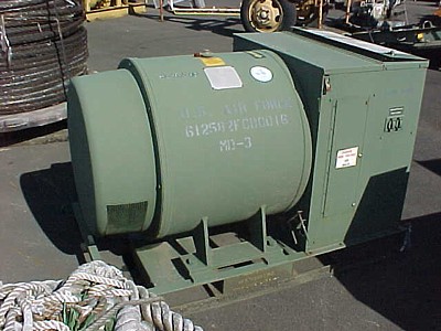
Because the Kohler genset is not really a perfect fit for our application, in a fit of idiocy I bid on (through GSA auctions) and won a surplus Kurz and Root MD-3 motor-generator set. These, I believe, were used to supply 400 Hz power to on-ramp aircraft. It is my hope that the 60 Hz motor end is synchronous and can also be used as a generator, and that there's enough shaft end sticking out to couple a small automotive diesel engine to. (I know it's a 1200 RPM machine, so a transmission will also be required. Less efficient and bulkier, but in a way much easier.) If it's an induction machine, characterized by not-quite-400 Hz output, it would be much more difficult to turn into a useful generator. (The 400 Hz end could supply resistive loads such as electric furnace heating elements.)
In the worst case I can strip it of its meters and such and scrap the thing. It's 2600# of iron and copper, I should be able to recoup a substantial amount of my $125 investment.
Message from GSA:
01/18 07090052 PM CDT A1FBPI06032787 You bought 1 lot at 125 USD per lot.
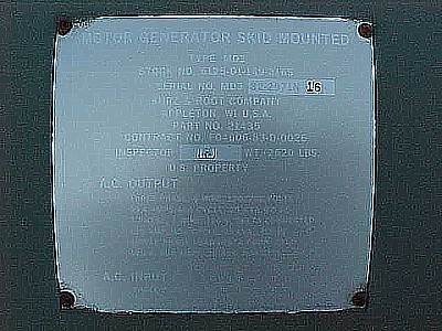
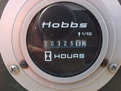
GENERATOR SET, SKID MOUNTED, MFG. KURZ & ROOT CO., MDL #MD3, 3 PH, 400 CYC, 25 KVA, 0.8 P.F., AC OUTPUT: 3 PH, 4 WIRE, 120/208V, 3 PH, 3 WIRE, 120V, 1 PH, SN: MD3 82-2971N 16, HOUR METER READS 20325.8, 2620 LBS. USED, WORKING CONDITION UNKNOWN, REPAIRS MAY BE NEEDED. (470496-5277-87; 01-261-09; 0S2)
THE CONDITION OF THE PROPERTY IS NOT WARRANTED.
Other Auction Pictures:
Wilton, LtCol, USAF, Ret.
Wilton
Wilton
The gal that processed my paperwork also loaded it with the forklift, was cute, and was friendly too! You single guys out there should maybe purchase some big things through the Salem, Oregon GSA office? Regardless, it seemed a pretty good job that you got to do both inside and outside work. Keeps you from getting stale.
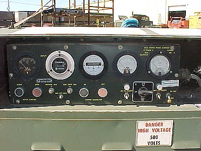
A cursory examination of the unit reveals a big fan on the outside end of the unit under the cover, the implication is that there's a shaft stub there that could perhaps be attached to. There is a schematic inside the access lid and I believe it shows wound rotors for both machines, so early indications of a double-ended synchronous nature are good.
Though it has plenty of hours on it (20,000+), the paint is in good condition and the rotor turned easily by hand.
Used the digicam, a copy stand, Photoshop, and Illustrator to start recreating its schematic.
The motor circuit soft-starts things by first connecting the windings in wye, then after a delay connecting it delta through series resistors, then after another delay bypassing the resistors. During all this both machine's fields are in series with a special supply winding, the field 'flash' function. After a final delay the fields are normally excited. Cool.
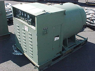
I opened up all the access panels, and the quality of construction and the general scale of things makes the Kohler genset look like junk, which it isn't. I love military surplus equipment!
Point 2 above is somewhat resolved, the G1, G2, & G3 phantom lines are the main 400 Hz generator output leads and so CT5 is taking feedback from the total current output of the generator. I guess the normal field excitation isn't enough for higher rated outputs, perhaps the regulator doesn't have sufficient range? Point 3 is also resolved, CT4 is just boosting the output a bit based upon one phase's output (assuming a fairly balanced load) to compensate for line drop getting to the load. Its response is adjustable on the front panel.
I began clearing a space in the garage for it. This will take days, there will be a lot of 'collateral damage'!
I bought two pairs of Harbor Freight's on-sale car dollies to serve as casters. The 2600# of the genset, before any engine is even added, would consume a lot of cheap 300# Harbor Freight casters at rated load. As they didn't work out too well for the Kohler (overloaded!) I'm trying this much-more-expensive path. The dollies (there are four, making for sixteen wheels) are rated at 1000# each, and I can also use them as car dollies as I don't intend necessarily to dedicate them to the generator. Certainly they're going to start out there, however.
Anyway, with it in place for the forseeable future I took the protective cover off the 60 Hz motor end. I found the heavy cast fan attached to the rotor with four big bolts, I think that a yoke could be made to attach there for an engine drive coupling. A complication is that the rotating heat sink disk carrying the field rectifiers and the mystery S11 'Electronic Switch' is in the way, mountings for these components would have to be incorporated into the yoke.
With the access to the fan I was able to spin the rotor up much faster than before, only to find a fair amount of bearing noise. If the bearing is shot I'm sure it will be an interesting time to replace it. I won't worry about it until far down the road, of course.
Given that it's actually possible to do quite well with a modestly-sized genny, I've been wondering about driving the MD-3 with one of those Lister-type engines? Very thrifty in operation, but the hefty mass of the motor and the generator would mean that it would have no problem with transient loads like motor starting. The Listers are quite durable. And I already own the MD-3. It's a thought.
I also generally hate batteries, so the thought of using a battery bank for riding out the night is repulsive. But what if you could cut the house loads to minimum and run the Lister at low RPM, while using the MD-3's 400 Hz windings to deliver 60 Hz, at greatly reduced power of course, and presumably reduced noise and fuel consumption. Possibly impractical, as that'd make the Lister run at less than 100 RPM for night duty, but an interesting thought. I found a site where I might learn some things.
Could the IR2136 and IR2175 be of any use for this? They may be too small.
By controlling the AC frequency with a variable frequency drive, you control speed. A proper voltage to frequency ratio (V/Hz) must be supplied. For most industrial motors manufactured in the US this ratio is 460 volts to 60 Hz or 7.6:1. I.e.: to achieve 10% speed, you should supply 10% frequency (or 6 HZ). To properly apply electric power at 6 HZ the output voltage of the variable frequency drive must be 45.6 volts (6 Hz × 7.6).and
The theory behind this is, motor speed is varied by changing the frequency, and motor torque is maintained by keeping the volts to frequency ratio constant (for most applications).I've also heard that a good rule of thumb is that an induction (slip) machine can go down to about 1/3 normal RPM.
So, with that math the 220 V three-phase motor (or generator) end of the machine should be able to run at about 260 RPM without saturating on 48 V, or at half that on 24 V.
1200×48
------- = 260
  220
This is well below the 1/3 normal point, but these are also synchronous machines so field induction isn't so much of an issue. Even 130 RPM should be well above what it takes to crank up a Lister. (I've heard that 60 might even do it, but that's well down in RPM, probably too low to use safely.)
48 V is attractive because that is a likely battery bank voltage for something like a Trace 5548. 24 V is attractive because that's only two separate starting batteries, not four. (The very attractive single separate 12 V starting battery is, alas, probably too lowly to do the job.) Using the main battery bank is particularly attractive because one of the generator's main jobs is going to be keeping that charged, so recharging a separate starting battery would be a non-issue. However, the battery bank would need to be able to supply starting current as well as its normal full-load operating current. That could be an issue with the deep-cycle cells usually used for inverter systems, so a separate starting battery (and charger) may well be necessary even if the system was otherwise voltage-compatible.
Another thought is to chop the waveform rather than drop the voltage in order to keep the magnetics out of saturation. Given an IGBT (or FET) drive such shenanigans aren't likely to be that hard. Better would be the ability to detect the onset of magnetic saturation and cut off the drive at that point in the electrical cycle. (Watch the voltage waveform at both ends of a series resistor and cut off when they stop tracking. Put another way: watch for an increase in drive current and cut it off.) Then the system would auto-adapt to whatever battery voltage you had available.
Some IR app notes: http://www.irf.com/technical-info/appnotes.htm