THE CONDITION OF THE PROPERTY IS NOT WARRANTED.

As a certified cheapskate, I was completely unwilling to pay the going rate for a genset that could handle the entire 225 A/240 V service to the house, for backup power. (We have electric heat, the furnace alone draws 28 kW.) I'd been watching GSA auctions for months, but everything was either too far away or ended up costing too much. (Converting the house to propane is possible, but would end up costing a fair amount too. Without a doubt the lowest-cost path was to find a surplus (cheap) genset large enough to do the job and with enough life left in it to serve.)
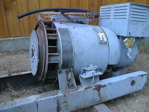
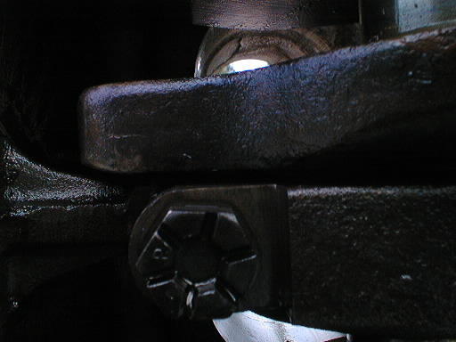
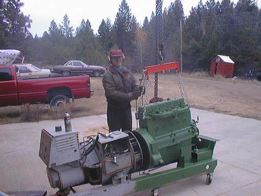
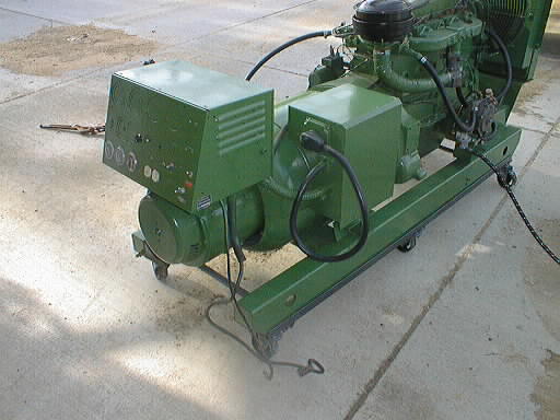
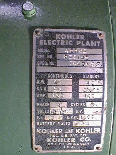
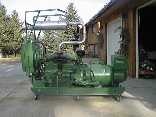
Finally one came up nearby, and my bid won it! For $404 I was the new owner of a 40 kW propane-fired genset located in Cheney, about an hour away. It is old, circa 1965, but looks substantial. 6-cylinder Hercules engine, Kohler 3-phase generator. The one unusual thing about it is that there is no starter motor. The 24 V DC exciter for the generator field is very stout, and serves as the starter motor as well. A heavy Lucas electric starter had been sitting on the generator for some time and I guess everybody assumed it went with it (it certainly followed me home). But it doesn't belong, there isn't even a ring gear for it to bite, and why would Kohler (USA) have put a British starter on the Hercules (USA) motor anyway?
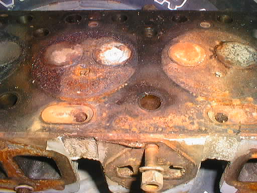
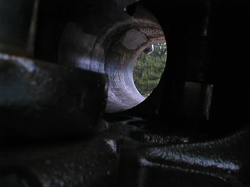
Supposedly it had run two owners ago, and while the previous owner (a wildlife refuge) had never used it it had been stored in a shed under a tarp. Well, there is a reason it was for sale. It was frozen and wouldn't turn over (by hand). So I took the head off and found three very rusty cylinders. In a shed under a tarp? I don't think so.
I was starting to think that an engine transplant was in the works. But it's not like that is particularly easy to do, either, given that the rear main bearing of the engine serves as the front bearing of the generator.
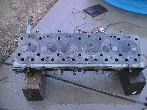
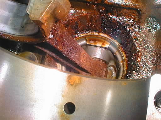
After learning about a very helpful tip on electric rust removal, I was able to remove the accessible rust from the three cylinders, exposing the cracked block that was the source of the water for one of them. (The other two looked like rainwater had gotten in.)
A local shop that knows about Hercules engines says it can sleeve the cracked cylinder for $100 or so, and a standard head job is about $250. But the remainder of the parts for a cheap rebuild are not cheap, and the whole job was estimated out (using mostly my labor I might add) around $2000! I'm still looking at my alternatives.
Pictures (in progress):
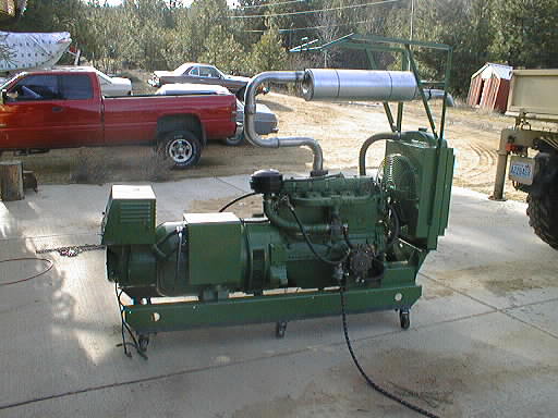
This was a lot of work, and significant expense. And assuming it all works, I've got a slightly-too-small generator that runs on the 'wrong' fuel, and is three-phase instead of one. All far from ideal. On the other hand, it's an extremely solid unit, and one that I've seen selling for $5,000–6,000!
(In fact it could be exactly the right size—if the house were completely re-wired for 3-phase! The various heating elements, especially the furnace, draw less power at 208 V than they do at 240 V, and there are enough individual elements within the electric furnace to spread them around the phases. A system could probably be worked out using a giant knife switch on the furnace and some seriously custom cabling, but the trouble and expense hardly seem worth it. Heating with wood during power outages has so far been entirely satisfactory.)
GENERATOR, ELECTRIC, MFG KOHLER, MDL UNK, PROPANE, 1 EA. REPAIRS MAY BE NEEDED. (1404D8-4099-0009)
THE CONDITION OF THE PROPERTY IS NOT WARRANTED.
...Here follows some random recollections, I wasn't keeping good records at that time.
However, there is a big crack in one of the cylinders. That's the water in it. The other two look more like rain, or at least condensation, got in. They were probably the ones that had open exhaust valves.
After checking that the field was getting voltage I checked the outputs and found a low AC voltage there, at maybe 20 Hz. I connected a car headlamp to each winding in turn, and when spun up the filament lit up (modestly), and throbbed at the low frequency. This proved that the magnetics were working, at least enough to risk an engine rebuild.
In keeping with my stated intent of minimizing the cost for a rebuild good enough for backup power purposes, they thought that the bearings were all reusable, but strongly advised against attempting to re-use the rings even though it was apparent that the engine had low hours on it. They said they'd never re-seat and seal, and not to waste my time.
It is up to me to find a ring kit, and a gasket kit. And to put it all back together. Assuming I can remember how.
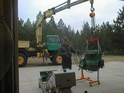
I had to use a floor jack to lift up the heavy (generator) end to get the frame underneath. A chain fall from the ceiling rafters lifted up the light (missing engine) end. For actually putting the engine back I think I'll hang the chain fall from the skyhook (Mog crane).
WD-40 and a rag was used for cleaning, and white lithium assembly grease was used on all the bearings. Some wet-and-dry sandpaper (and WD-40) was used to remove the odd bits of surface corrosion on bearing surfaces.
I also cleaned up the one piston I'd taken apart.
In the afternoon I went shopping. NAPA didn't have a front main seal, but I did pick up a roll of gasket paper and a tube of black RTV gasket maker, the good stuff. The local bearing supply house was able to supply a seal. But, they didn't have any wrist pin keepers (one of which I've broken). A driveline supply house also didn't have anything suitable. The engine rebuilding house I used for the machining had one used one they gave me, but I think it might be too thin. They said to call Tuesday if I wanted new ones and they'd talk to their Hercules guy to see what he could come up with.
I managed to knock two screws down into the block, and I had to pull the camshaft in order to fish them back out. It had to come out anyway to put the timing vault in place.
While I was out, I stopped by the engine rebuilding place to get them started on looking for wrist pin retainer clips.
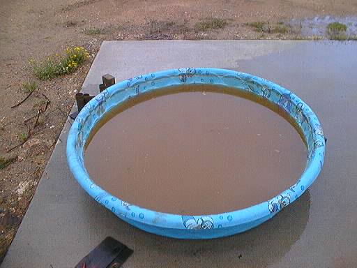
The front pulley was very rusty, especially where the belt had been trapping water, which of course needs to be smooth! So I've placed the pulley in a bucket and am employing the electric rust-removal trick, using a sacrificial anode wire bent to encircle the pulley's groove.
Out shopping today I dropped off a good wristpin retaining clip at the engine rebuilding place, so that they can try to locate equivalents. I also bought that other 10 gallon LP tank. $40 for this one (it's less full). Though getting more than a couple of hours out of one is unlikely, they've still got other uses, such as refilling small tanks (courtesy of the liquid feed). And I have one in particular I'm interested in keeping going: a small 2-gallon one that I use on the weed burner. Non-OPD, refill places now won't touch it. And as an odd size, a new one is not cheap. (Heck, it wasn't all that cheap in the first place.) I'd spend as much on a new baby tank as I did on the forklift tank I'll use to fill the old one.
I scanned my deteriorated generator schematic (it was pasted inside the control housing) and began re-creating it using Illustrator. (I put the 52 MB scan file in as a semi-transparent tracing layer.) Wow, this is tedious! My intent is to recreate it as accurately as is reasonably possible. (Partly as a test vehicle for learning Illustrator, but mostly because I have a suspicion that I'm really going to need it. I had located a faxed copy of the original drawing, but fax duplication is far too coarse to show all the necessary detail. It's nearly useless, but using it I was able to piece together the stuff from the missing parts of my original schematic.)
The one problem I had (other than Illustrator's learning curve) was that the Mac kept crashing, but only when it got heavily loaded. I theorized that one of its three memory modules (256 MB, 64 MB, and 32 MB) was bad, so I started removing and reinstalling modules. With only the 256 MB installed, the system worked fine (yay!) but was a little boggy. (With anything less than 256 MB it's doubtful that the system would be usable for any serious work.) With the 64 MB added to the mix, it still would crash. Substituting the 32 MB for the 64 MB resulted in a less boggy session, and no crashing. It appears that the 64 MB module is bad, and needs to be replaced. Preferably by something bigger. As Jill's iMac also has only 256 MB, and she's the one that's really going to stress her computer, we'll need to get more memory for it too.
I spoke to my brother, and given the high price of new wrist pin clips, he thinks that reusing any that are determined to be sound is reasonable. So I plan to remove all the clips to see how many break, and then order replacements plus a couple of extras. (I've already broken one.)
...The engine rebuilding shop said that while their original vendor wasn't interested in selling partial sets, they'd found another place that would sell the entire set for $21. That's about what I was going to pay for the four clips I needed, so I told them to go ahead. Unfortunately it'll be awhile before they get in.
We had been scheduled to pick up a piece of hierloom furniture from our relatives as well as my modest load of six items. I'd thought about bringing the car trailer as well as the empty pickup, but because the dog run we had also wanted had already been claimed by another relative, I figured the truck alone would hold everything we were bringing home. Once I got there, the worry started. These things were big. Very big. And heavy. Eventually they got both pallets loaded using their forklift, but we had to leave the tailgate down, and one of the original pallets wouldn't fit into the truck. We had to transfer the one big Zenith switch to another smaller pallet. (I did bring home the original pallet, which was very stout and made of 2×6 lumber. Stacked on edge along the side.) We then drove over to the relatives' house for our visit, and for me to think things over.
All items but the one big switch were small enough to be manhandled by one guy, and light enough to be carried by two. One was even light enough for easy carrying by myself. So I spent an hour rearranging the truck to try to make room for the shift. The big Zenith switch was too heavy for me to shift. I made some headway, but it looked iffy to me. The furniture was buried in the corner of the garage, so I didn't get a real good look at it anyway.
To save money, I'd arranged for this trip to be an economy run. On one memorable occasion before I'd managed in excess of 26 MPG in the truck, the secret apparently being to go slowly and on its original (narrower) tires. So earlier in the week I'd removed the big wide wheels and tires I'd put on for stability when hauling the camper, put back the stock ones, and told my wife to prepare herself, and her rampant impatience, for a slow trip. On the way down I'd set the cruise control so that the tachometer read 1800 RPM, a figure I'd heard was the efficiency peak of the Cummins. About 58 MPH, we were passed by everybody. (Just like the last time I remembered.)
Because the fuel gauge sender is flakey (a well-known weakness in Dodge trucks of this vintage: for example as we came down the hill into Yakima the reading fluctuated slowly between 1/8 and greater than 1/2 of a tank) we were unable to reliably tell how we were doing fuel-wise, but it looked good to me. I find that the gauge always reads low when it's lying, I've never had it read higher than seemed plausible. Besides, the truck has a 35-gallon tank, and I've never yet needed to put more than about 20 gallons in it.
The slow trip home was uneventful, though the low fuel light did come on at times. (And then it went up to 1/4 of a tank.) Unlike the Mercedes fuel sender, which uses a separate contact for the light for some semi-independence, the truck just measures the voltage out of the sender to trip the light. Since the sender lies, so does the light.
We went directly to my favorite fueling stop, and when my wife had finished the logging (about 475 miles, and 18.5 gallons) and I'd asked her how we did, she looked sheepish and mumbled "25.7". Score! She'd been griping about the slowness of the trip the whole way, but I think she appreciated the fact that this trip cost us nearly half what it might have.
I attribute the slightly lesser mileage (than the all-time best) to the fact that this time there was an extra trip home included (my record run was a fillup on the way out to a fillup on the way back, so the entire record trip was warm freeway miles), four stops in the middle (including the overnighter), two sessions of stop-and-go in Yakima, the fact that the AC was on for about a quarter of the trip, and the weight and bulk of the load in back. Still a pretty good result, IMHO.
Out of this I expect to use the disconnect switch, and one of the 200 A transfer switches. I don't expect its automatic features to work, I'll be more than happy if the switchover is a manual process (whether big handle or toggle switch). But you can't touch this stuff new for $60, I'll tell you that! According to the guy loading the stuff, it wasn't dead or anything, just old and superseded. But stored out in the weather for awhile.
The rest will be scrap, or spare parts or something. The big boxes might be nice, with a little paint.
For the time being, I've taped up the holes in the boxes (to keep the weather and bees out, etc.) and have stacked them on their pallets out of the way.
When asked, the guy at the engine place asked "How much you going to drive it?" That's not a good sign!
Some of the other pistons, untouched by me, showed that all three bores are of approximately the same looseness. So, I think in the worst case a gentle honing of the one connecting rod bearing will do the trick. We'll see. It seems clear to me now that this engine doesn't have any weird restrictions about disassembly. This is what I would expect from an old, low-tech industrial engine.
I also removed the rings from three of the pistons. This doesn't sound like much but believe me it's a real treat! #1 had already been done, so I did #'s 2–4 today. #2 came apart no problem, but 3 & 4 were the rusty ones, and they were a real chore. Most came out with careful scraping, digging, and tapping with a hammer and a small screwdriver, but one had to be pried out in a lot of little pieces. These two pistons are now sitting in the solvent tank. #2 went through the whole cleaning process (scrub brush) and got new rings. I cut a section of metal banding (from a lumber delivery) to use as a ring compressor, and put #2 into its bore. (Just using the strap of springy metal with 90° bends in it [ears for clamping on], some oil, and a pair of vice-grips. I'd successfully used this technique earlier on a tiller motor. It took three compressions [easy] to get a piston in. Once for the bottom ring [of four], once for the next two up, and once for the top ring. The only trick is that the top ring has to be installed in the piston after the piston's mostly in place as the band is a little too narrow to clamp the top three rings all at once, and the top ring, if in place, will prevent the piston from going in the bore when doing the middle two rings.) The piston's home, but the bolts are not torqued yet.
I reused the original wrist pin clips, the ones that had not broken upon removal (the rusty ones) seemed perfectly fine: they're solid and at least fit correctly. I'm not sure what to do for the three broken ones, one option is to reuse them anyway as it's only the removal ears that are broken off. They'd be a bugger to get into place, they certainly were to get out! Another is to put in the new ones that are too thin, but glue (green Loctite) them in place (the suggestion of the engine place).
Removed old rings from, cleaned, put new rings on, and installed pistons 5 & 6; they were no problem. Neither even needed the ring grooves scraped out since these weren't the 'wet' cylinders. Just a gentle scrubbing in the solvent tank and they were nearly as clean as new ones would be. I remain convinced that this was a low-hours engine that had merely been neglected.
#1, the problem piston with its tight rod bearing, was last. I examined it carefully and decided that the real problem was that I'd somehow managed to raise a slight ridge inside it, as the wrist pin would slide in from either side to a point where you could see a faint line. So I used a piece of that worn wet-and-dry sandpaper, wet with oil, wrapped around a socket as a hone. I was able to take down the slight high spot enough that the wrist pin slipped easily through. Afterwards, this piston felt like all the rest so I had no fear that it was going to be an ongoing problem.
I then screwed in the four head studs that the machine shop had removed when sleeving #1. I used a pipe wrench.
Finally I torqued down the rod bearing caps and called it a day. The engine turns over nicely using a wrench on the pulley nut.
Torquing down the head was somewhat difficult as it's done in three stages, with the last one being 175 lb-ft: a real pull! My good (beam) torque wrench only goes to 100 lb-ft, but I had another cheaper beam wrench that went to 140, with enough unmarked travel off the end of the scale to get to 160+. So I used it and guessed. You really have to put your back into it. It was like rowing: feet on the engine stand, both hands on the wrench, and body at something like a 45° angle, all while craning your neck to try to read the wrench's scale! Add to this the fear that the wrench will slip off and you'll launch yourself backwards onto a car or pile of junk, or that the engine will break off the cheap Chinese engine stand and crush your legs...
Of course, there was no problem, and it went smoothly, but I am wishing now that I'd bought the heavier engine stand, this one is groaning under the strain of the heavy Hercules.
Putting on the rocker arms was difficult, as the holes in the thing didn't want to line up with the studs (concentric with head nuts). Not to mention that the rocker bar is in two pieces and you really need about six hands to manage everything. But with enough fiddling around and tapping with the brass hammer it eventually went together. Still a royal PITA, due to all the springs and separate pieces.
I next set the valve lash to 0.016", cold (very). They were initially very tight, what with all the mucking around. (Valve job, new head gasket, etc.) I wire-brushed off the valve cover, and gave it a first coat of rattle-can green. I'm planning to reuse its cork gasket, which is intact and looks decent, though I may need to use a bit of sealer on it. I won't seal it until after the engine runs in enough to check the valve lash again.
I then drove the rear main seal out of the bell housing, and rounded up one of the rusty spark plugs. Time for a trip to town!
...No problems in town, a new seal was $27 at the local bearing supply house, and spark plugs were about $9 at NAPA.
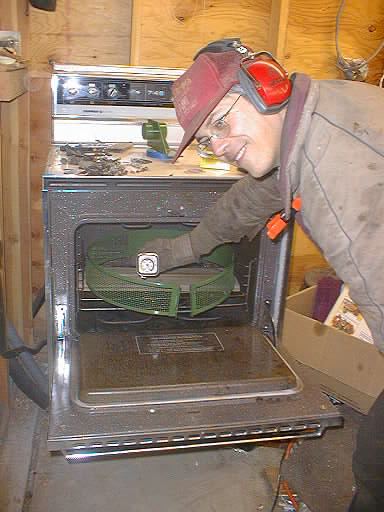
I scrubbed off the greasy bell housing with TSP, and then wire brushed it. I blew it off and put it in my shop oven to dry. (I am so glad I didn't let my wife get rid of the old kitchen oven.) It hung out the door quite a ways, and was almost heavy enough to collapse the racks! I then got out a radiant shop heater that I'd bought but never set up and put it and the spare propane tank out in the greenhouse, and then humped the now-dry (and rather hot) bell housing out there. The greenhouse is bright (at least during the day), spacious (since it's winter), and (with the heater) warm. Not a bad place to do some painting, and there's no risk of overspray getting onto one of the cars. It's too cold to paint directly outside, my usual practice, not even considering that it's snowing today. I'm painting the engine side of the bell housing, since once it's attached it would be difficult to paint that side cleanly. More rattle-can John Deere green.
I also wire-brushed the rust off of the old spark plugs, they went into the holes for when I paint the engine. The intake manifold also got wire-brushed, and then I put the valve cover on and painted the manifold and head, along with the ends of the engine block.
To put the bell housing on, the engine needs to come off the stand. I put two long scrap 2×8's on edge in the rafters of the garage, near the side and spanning four of the rafters, and nailed up a couple of scraps of wood to keep them on edge. I then hung the chain fall from this and attached the as-yet-unused load leveler I bought awhile ago to the chain. The engine's head had four nice big tapped holes on the ends, perfect for screwing the leveler's four chains to. I attached the chains (temporarily using the bell housing bolts until I can purchase some for the purpose) and lifted the whole assembly, engine stand and all! It came right up off the ground, and was even nicely level. This will work out fine. While I still plan to use the Mog's crane to install the engine, I can't really use that to hold the engine up in the air while I work on it over time. For starters that would have to be outside, and the crane leaks down when left alone for awhile. Both are bad characteristics for the job.
In the evening I went to town and bought four more bolts for lifting the engine with.
I next cleaned off the gasket area of the bell housing, and cut a new gasket for it. I put the bell housing into the oven again to warm it up, and then installed the (cold) new rear main seal. Then I bolted the bell housing to the engine block.
Finally I did some touching up with the green paint. The engine looks mighty nice hanging there. Big problem: how am I going to put the engine back on the stand so I can turn it over to work on the oil pan? The engine stand arms won't reach all the bell housing bolt holes, and they're awfully small anyway. I've left the manifolds and flywheel off to keep the engine weight down, but hanging this mass of iron from only four of twelve small bolts is a frightening prospect.
In the evening I went to town and bought four spindly little Grade-8 bolts: 3/8" × 3". We'll see if this will work out. I'm still thinking about it.
Of course, this still leaves the engine attached to the stand via only four Grade-8 3/8" bolts, which is a bit disconcerting. However, I theorized that they're more than strong enough, if it weren't for the stress caused by the engine being cantilevered off the end of the stand. I did carefully lower the engine's weight onto the stand, and it didn't collapse. So, to alleviate the stress I looped an old 27" bicycle tire (a would-be tug-of-war dog toy, except that the dog won't have anything to do with it) around the shaft of the pulley and hung it from the chain fall's hook, and then lifted that end of the engine until it was level again. That makes most stress on those four bolts be shear stress, which should greatly eliminate any chance of disaster.
I then rolled the engine over so that I can work on the oil pan, and set the pan on it to keep out dust. Then it seemed like a good time for a break.
In the afternoon, a second coat of paint.
Using the rafter hoist, I rolled the engine back over, hanging it from the head again, and removed the engine stand. Then I cleaned up and put on the flywheel, torqued it down, and threaded the (new) retaining wire through all the bolt heads.
Next was to install the exhaust and intake manifolds. I reused the exhaust gaskets, and used the RTV for intake gaskets. The exhaust studs got anti-sieze compound. One boo-boo: I initially installed the intake manifold upside down. I'd forgotten that the carburetor hangs from the bottom rather than sits on top. Three of the manifold nuts are missing, I'll have to find some more. The last step was to install the distributor heat shield.
This puppy is nearly ready to attach to the generator now. It's bee-youteeful hanging there on the hook. Still plenty of work to do, though.
I then dragged the rest of the generator system out of the corner to prepare it for painting, and found that the solid wheel tires under the heavy end have developed flat spots. Bummer. I also found the old oil-pan end seals, tucked into a crevice in the frame. Those would have been nice to have earlier! I'm toying with the idea of popping off the oil pan and redoing it using these seals, there's no way I want to risk a pan leak given how much more difficult it would be to repair once the engine is installed.
Anyway, in the afternoon session I cleaned and then painted (first coat) the empty engine-end of the skid.
Today's shopping trip netted me three more manifold nuts, and another tube of goop.
I also pulled off the intake manifold. I was not happy with the way it sealed down before as two (of five) of the gaskets had somehow gotten lost along the way, so I'm going to make some gaskets for it out of the gasket paper.
I also put another coat of green onto the half of the skid that I've been painting.
After breakfast I went back out and cut out the two new intake manifold paper gaskets I needed. Then I put the manifold back on. (And again managed to start putting it on upside-down. Sheesh!)
Because I'm planning to install the engine today I also began cleaning the screen that goes over the generator fan. It was very gunky and caked with greasy dirt, and was easy to slip off the end of the generator while the engine was still removed. Much easier to clean separately rather than in-place.
...OK, I'm thankful I have a crane! I dragged the engine outside on its stand, and the rest out on its dolly. I then hung the engine from the skyhook (the Mog's crane), and lowered her in, using a chain fall, the load leveling bar, and a hydraulic jack on the tail of the generator to get all the angles right. Then I crept them together by lowering the chain fall and dragging the dolly into position. The worst part was getting the oil drain/fill pipe through the hole in the side of the skid, I ended up having to remove one of the motor mounts on the generator so I could pivot the whole assembly around the one remaining mount. (Maybe getting out the pipe wrenches would have been easier.) Anyway, with enough fiddling and trial-and-error, I got the thing in place and fastened the 8 flywheel bolts and the 12 bell housing bolts. Then I lowered the whole assembly onto the motor mounts. The engine turns over nicely with the wrench.
I'd even remembered to put the (painted) screen back on first. (Hey, this turkey's just about done.) It would have been harder to put in place after mating the two big parts.
Putting the thing away (so that I could deep-fry the bird) was a pain, the assembly is too heavy to roll on the dolly. The yard tractor just spun its wheels trying to drag it, so I extended the Mog's crane arm all the way out so that it hung beyond the generator, attached the chain and dragged it with the Mog. Dragged, even though the Mog was on the push side of the thing: the crane's boom extended over the generator to pull from the other side. This kept it from spinning around, which is what happened in my first attempt when I was just pushing against a plank wedged against the pulley. Dragging got it most of the way into place, but the crane is too tall to go all the way into the garage. I took another run at it by pushing with the crane against the plank to get the last foot or two. What a pain!
I tanked the carburetor and cleaned off all the gunk, then installed it. Now I can see all the cast markings for the various adjustments. The throttle link rod now has one coat of green paint on it. I attached the air filter bracket to the head, and cleaned and painted the oil-bath air filter housing black (and which is drying in the oven). I've begun to clean off the water pump, which was very rusty, and to attach some of the water fittings to the block. One pipe nipple had broken off inside its fitting (before I got it), and I'm going to have to drill and tap it out. Attempts to file and chisel it out failed. I'll probably need some more tools for that.
...At Harbor Freight I bought a set of large twist drills and a pipe tap and die set. That ought to do it.
The drills and tap actually worked, the water fitting was restored to goodness. It didn't hurt that the broken-off nipple was brass. I then painted the fitting, cut out a gasket for it, and put it on the head. Then the whole area was painted again, which picked up the gasket edge and the bolt heads. I also attached the now-painted air filter housing, and cleaned and painted (black) the washable element, part of which shows. I put another coat of paint on the throttle rod. I also duct-taped the ratty intake air hose, and installed it. Not beautiful, but it will serve for now. I think I'm going to have to make a big purchase at the hose shop sometime, most of this stuff looks pretty tired.
After breakfast I went back out and cleaned up the remaining piece of the throttle linkage (a pivot block and spring). That was a pain due to lots of little crevices, the Dremel was part of the treatment. I painted it and put it in the oven to dry. I next did the drill/tap thing to get the other end of the broken nipple out of its T fitting, and then brushed and painted that fitting assembly. (It's for the block heater.) I then cleaned up the thermostat housing, made a new gasket, and installed the thermostat. The housing got painted, too. The air bleed hole in the thermostat housing was plugged, so I made sure to clean that out. The thermostat itself has a slit in its flange which perhaps serves the same purpose, so I also made sure to point it upwards.
My wife brought me a new brass nipple from the store when she went out. It may be too short, we'll see.
... I managed a second coat of paint before I went to bed. Should be ready for use in the morning.
Then I wire brushed the radiator housing and its shell, and rattle-canned a first coat of paint on it. It's three rather large pieces (not including the inside wire fan shroud), and is going to take some handling to finish.
...Later I put another coat on things, and stood the radiator up in its place. It's actually easier to paint most of it that way.
And then on to the generator end and trying to get this thing to run.
I pulled the spark plugs and tried 'starting' it again. No joy, so I put a wrench on the tail of the exciter and twisted at the same time. It didn't take much of a twist and the set started turning, about a half second before the batteries died again. I really need new batteries!
...I went out and bought two used batteries at the U-Pull. $26, I hope that this will cure the problems for now. When I got home, I put them on the charger for tomorrow. I bought the two biggest batteries they had. Not matched in size, c'est la vie.
So, I then disconnected the starter solenoid and hit the Start switch. (I didn't want the engine spinning and sucking major juice during this testing.) The oil and water gauges jumped to their zero marks, a good sign. I also was getting power to the ignition coil and the fuel solenoid. Good! After some time 'CLICK' and it all shut off. Even the start timeout relay was working, and resetting it (by hand) brought things back to life. Excellent. (This same time-delay relay [1TS in the schematic] is tripped by cranking, by low oil pressure, and by high water temperature.)
I then reconnected the starter solenoid and hit Start again, while holding the coil lead near ground. No spark. I tried to use the meter during cranking to see if the points were working, but it didn't really act like it. (It's hard to tell when using only a general-purpose DMM.) So I shut it down with the points block in the flat of the cam and measured the resistance of the points, which was infinite. Even pushing the points together yielded nothing. So I got out the point file and gave it a few swipes. This restored the points to normal operation, and cranking the motor again resulted in a nice fat spark jumping to the block. I put the cap on (temporarily—no rotor) and figured out the routing of the plug wires based on the #1 I'd scratched in the side of the cap, the natural bends of the wires, their lengths, and the firing order (1-5-3-6-2-4). We're getting closer!
I then got out a bright light and a test light and tried to time (statically) the ignition. I found the 1800 RPM timing mark (handily labeled "1800", as opposed to the "1200" mark), and lined it up with the mark on the bell housing and tried to set the points-opening point for #1 at it, with a little bit of centrifugal advance applied. I don't know how close I came, but it should be close enough to run at least some. Cranking with the timing light doesn't show the mark, but I'm not sure what that might mean. Once the engine is running at speed I should be able to dial in the timing.
...Out shopping today I picked up a case of cheap oil ($0.50/qt on sale including rebate) and a Fram C4-P filter, for break-in. Also some other goodies like a battery disconnect and some heater hose at the liquidator's. (Sadly, 3/4" and not the 5/8" that it looks like it needs, but I can possibly make it work.) And a can of starting ether.
Hmm, what's left? Not much! I started it cranking, grabbed the can of ether, and gave it a few snorts. B-DDDD-AAAA-PPPP, it fired! This is a very heartening sign. I still need to rig up the fuel and cooling systems. Both promise to be a bit messy.
The spongy (needs replacing!) fuel delivery hose to the carburetor is 3/4", so that wrong-sized heater hose will have at least some utility on this project. The extra available length will come in handy for mounting the vaporizer in a little more secure position than it was originally.
...Out shopping today I picked up two replacement 2×24" corrugated coolant hoses, I was unable to find molded hoses that would fit. $25 each at NAPA, and that was with the AAA discount! But they're exactly what was there before, right down to the manufacturer: Gates. (OK, so the stripe is now yellow and not green, big deal.) Also procured was 8' of 5/8" heater hose for the fuel vaporizer and block heater plumbing. I was unable to get a molded 1×5/8" water pump bypass hose, that is going to take some doing. It's still intact but is getting kind of soft; it definitely needs replacing. The two different end sizes are the problem, it's a greater size spread than most of the hoses in the catalog. One option is to find a 1" hose that's molded right and use a collar of heater hose to shim the small end. Another would be to use hard pipe to do the routing, and just use short straight rubber bits to do the hookup.
...I got the Hotstart all painted and reattached, and I used new heater hose to plumb it in. Looks nice. (It's not wired up, I'm not sure that I would be using it anyway. It's a fairly high-powered item and thus not something I'd want to run all the time, yet when I'd need the generator there wouldn't be power [nor time] to run it. If it can crank over when it's really cold I'll probably just rely on ether if it has troubles getting going. Another consideration is that there's a nice block plug on the other side of the engine for a screw-in heating element, and those usually use half the power for the same effect as one plumbed into the heater loop like the Kim. On the other hand, the Kim is already there [paid-for!], and sometimes getting those block plugs out is a severe trial.)
Next up: the fuel system. I don't like the way the vaporizer was put in, and it looks to be upside down (not that this probably matters much). I'm going too see if I can rectify this, but all the plumbing will be severely disrupted if I do.
I read on-line that the IMPCO converter should be mounted right-side-up in order that trace impurities in the propane supply don't collect inside it. Ideally it's mounted above the carburetor so that said impurities run down into it and are consumed in the engine. That wouldn't be convenient here, but I can at least get it mounted right-side-up so it doesn't fill with crap, and the uphill hose to the carburetor could be opened and drained occasionally if there were a problem with impurities collecting. That's got to be easier than dismounting the entire vaporizer in order to turn it over and dump it out. I don't expect much in the way of accumulation in a backup generator, but at least what there is won't sit inside the guts of the vaporizer where it can perhaps do harm.
To actually turn it over will require removing a pipe nipple that's in the exit side. (The two water fittings seem to be symmetrical.) This nipple is the mount for the separate water thermostat for the vaporizer, which has to be on the exit side.
This particular vaporizer has an embedded solenoid that doesn't appear to have been hooked up in this application. I wonder if this is a priming solenoid. Current IMPCO documentation on the Model E vaporizer doesn't show any such thing. One on-line source (with a photo that looks like mine) called this an 'electric choke', but also implied that it enables a small unregulated propane flow. Prime? Choke? Whatever.
I also cleaned off the Century combination filter/fuel shutoff. (Sure was a lot of grunge on this generator.) I think I will mount it solidly to the genset's frame next to the vaporizer. Mounted 'properly', these two items will need longer hoses and pipes than they had before, but I think I'll be happier with them that way rather than hanging off the carburetor by a hose and tethered to the frame with a rickety network of scrap metal pieces.
I drilled new mounting holes for the vaporizer and fuel cutoff. I only broke one drill bit! (Grrr.) I then ground off the sharp bits and re-painted the metal.
Lastly I hooked up an old throttle spring to hold the throttle butterfly at idle. I don't want this thing to rev up until I'm sure the governor works. Overrevving could destroy the generator, or even the motor. Not something to play around with!
...Out shopping today I picked up mounting bolts for the vaporizer and fuel cutoff, some copper fuel tubing to reach between their new homes, and some pipe fittings to redo the oil drain pipe. I already have some 3/4" heater hose that looks like it'll work nicely for the longer vapor hose between the vaporizer and the carburetor. The existing hose is fabric-covered, but is too short and is all cracked and oily.
Then I unhooked the R12 filter/drier that was on the end of the LP hose and cleaned out the junk that had gotten jammed into the open end. I could replace this, but I think that if I heat it and put it under vacuum I can restore it to usability. We'll see.
I dug out the oil pan heater bar. I need to clean and paint its bracket and install it. I don't expect to need/use it, but I do like everything to be complete. It's the last piece off the thing to go back on.
Finally I got out one of the two forklift tanks and removed its exit fitting. I'll take it into town to see what I can come up with in the way of a mate to it, and maybe a couple of dust caps (one for each tank). I'm taking the flare fitting from the end of the LP hose also, as that is to be the other end of whatever I come up with. I'll take this junk, along with my one unreplaced molded heater hose, to House of Hose to see what they can do for me.
I'm getting close!
...Out shopping today I got a mating fitting (ACME) to the propane tanks, though it doesn't go on the fitting I took to the shop because it has a ding in it that I need to remove first. (Or so the clerk said. Supposedly there's nothing else that looks like that fitting except a BBQ tank, and this is not supposed to be a BBQ fitting.) I bought new sealing O-rings for the tanks because the one in the fitting I brought was nicked. The clerk said they seemed old and hard, so two new ones were appropriate. House of Hose has nothing in the way of molded coolant hoses, so I also picked up a sort-of-will-fit 1" molded coolant hose at NAPA. I should be able to stretch it into place and shim it (down to 5/8" on one end) to fit using heater hose. If not, I'll return it and think of something else. Goodwill also sourced an old pressure cooker that I hope to make into a vacuum tank for dessication of the R12 filter/drier (and other vacuum projects in future).
Plan B: Use the BBQ tank for fuel. I'll only be running at idle, and not for very long at a time so a vapor (rather than liquid) feed ought to work. So I hooked it all up and started cranking the motor.
Nothing. Though a snort of ether resulted in firing, so it seems that I'm not getting fuel.
Nuts. I then began a round of pulling off fittings to see where/if fuel was getting in. I could get a puff of propane out of the vaporizer, either by sucking on it or by pushing the prime button, but no continuous supply. I then started disassembling backwards towards the tank, looking for restrictions, etc. I even opened up the filter/cutoff (and found no filter element in it). Cracking the tank valve resulted in only a short puff from the straight hose into the filter housing, then nothing. WTF? I removed everything but the fitting, and found that apparently new BBQ fittings also have a flow check valve in them. I pulled it off the tank, and so long as you suck or blow gently on it air will pass, but do it harder and it corks off. CRAP! This fitting is useless, so back it goes for sure.
Plan C: The leftover 1' section of new 5/8" heater hose fits fairly snugly over the flare fitting on the fuel cutoff, and also the stub where the ACME fitting goes on the tank. It's also long enough to reach. So out come two hose clamps and voila: we have a liquid feed to the fuel cutoff. Cracking the tank results in a nice blast of propane into the filter housing. Yeah, baby!
I then put the fuel system back together, checking as I went. The fuel cutoff works, as it happens. With it all back together and the cutoff energized, sucking on the hose from the vaporizer results in propane flow, but nothing comes out otherwise. (Unless you press the prime button in which case a burst comes out then stops.) Looks good!
With the system all put back together I flipped the switch. Pooka-pooka-pooka-pooka-BLATTTT-budda-budda-budda... It runs! A nice idle, even. A bit loud, of course, since there is no muffler. Flip the switch off and it stops. This is great!
If I'm going to run it for more than a few seconds at a time I need to fill it with coolant. I tried to fit the new hose, and it just won't reach. Great, I have to return it and figure out something else. I installed the old hose so that I could fill it. I got a bucket and put in a measured two gallons. Yum, more please. (Oops, left the drain fitting open on the block. Easily closed, and I only lost a cup or two.) Another two gallons.... and two more. The last pint of the six gallons doesn't quite fit. Man, that's a lot of coolant capacity. I did it this way for three reasons: if there's a leak I want it to be water and not antifreeze, I'll need to replace the old hose and I'll probably make a mess doing so, and I need to know the total coolant capacity so that I can know how much to put in for a 50% mixture. Later I'll drain off three gallons and put in antifreeze. (I only bought two gallons for this thing, so I'll have to get another.)
No sign of big leaks, so I fire the generator up again. It idles for awhile, and I even run the throttle up a little. Seems smooth enough. (The fan on the generator blew out some pine needles at the higher speed.) The oil pressure gauge reads 40 PSI. Everything is going well, then it dies. I look, and find that the thermal cutoff switch (the overcrank/overtemp/underpressure breaker) has popped. I'll have to dig in to find out why it did. Possibly one of the temperature or pressure safety senders has failed.
Still, this is a very good sign! I've got a lot to do yet, but we're on the way. Time for breakfast.
...Out shopping today I returned the molded hose and bought some 1" straight heater hose and some copper water pipe and fittings. We'll see if I can fabricate a new coolant pipe out of hard pipe with two short rubber hoses for hookup. No place that sold propane junk was open today so I have to stick with my hose clamp fuel supply. I was also unable to find my two gallons of antifreeze, so I bought three more.
Looking at it this evening it is apparent that the LPG is attacking the heater hose, it's seeping through at the band clamps. So, this will not be a good solution even for the weekend. But we'll get by somehow. I released the pressure and removed it so that I can put it back on for demonstration purposes later. But it's obviously not to be trusted unattended.
There also might be a slight coolant leak at the middle of the intake manifold. I suppose it could be the head gasket, but I'm wondering if the middle section of the manifold, the carburetor perch, is heated by a coolant passage? It has holes into the head, and somehow I'd thought it was exhaust gas, but it could well be water instead. I didn't do a real stellar job on the intake manifold gasketing, and it would be easy to pop that off and try again. I'll keep an eye on it for now.
So I fired it up again and measured the voltage across 3CR's coil, and it was only something like 5 V. When I revved up the motor some I could see 3CR and 2CR's armatures pull in, and the voltage leapt up to something pretty close to 24 V. Once these relays have actuated, the Start/Stop switch no longer stops the motor immediately, but instead uses the TD timer relay to induce a two-minute shutdown delay. Cool, everything seems OK so far but I'm going to have to hook up the governor if I want things to behave normally. I traced the coil wiring from 3CR, and what is there does not correspond exactly with the schematic I have. Great.
I next hooked up a tachometer so I could keep an eye on the RPM. The thing was idling at something like 600 RPM and I could tug on the throttle to run it up to 1800 or thereabouts. When I did this I could see the governor lever move back and forth so it seems like I did get it back together correctly. With great trepidation I put the throttle rod back on in place of the spring and fired it up again, this time with my finger on the emergency shutoff and my eye on the tachometer. With a roar it fired and shot up to 1800 RPM and leveled off. No problem whatsoever, it runs very steady at speed.
At speed I could measure about a 13 A charging current to the batteries, dropping off gradually with time. So that part was working correctly too. Battery voltage was about 27 V at that time.
Next I paint-marked the 1800 RPM timing mark on the flywheel and hooked up the timing light. With the motor running I adjusted the distributor to center the mark in the window in the bell housing. It wasn't all that far off to begin with, the static timing process must have worked.
I then hooked the Fluke to the AC terminals that are inside the control box. (For the panel outlets, hour meter, etc.) There was power there which was good, and it measured 61.5 Hz so the motor is running a hair fast; no big deal it can be adjusted later. Much more disturbing was that it was in excess of 300 V! I don't think the regulator is working, which is no surprise given that the regulator's C & D terminals aren't hooked up. (Cut wires, big ones.) There is no Regulator rheostat, which the schematic and wiring diagram imply ought to be there. I also measured 300+ V on two of the main output terminals in the wiring box.
More disturbing than this is that the head gasket very definitely is leaking. Water is seeping out on both sides. Sigh. The head was torqued down to 175#-ft in three stages, over a new dry gasket. I wonder what is wrong? Useful reading found on the internet was this link from Babcox.
So I drained the coolant and removed the head. (Easier said than done! Before I pulled it off I checked the torque on the nuts and all were OK.) I left the manifolds on and used a chain fall from the rafters to lift it off the block, it's just too heavy to handle by myself without risking damaging it on the studs, etc. The head gasket picked right off, it wasn't stuck very much (yet). No obvious smoking guns, though #'s 1–5 had signs of rust on the head in the combustion chamber areas, I'm guessing this is a sign of water leakage getting into things. Or maybe this is normal and #6 just wasn't firing?
Thoughts:
...Out shopping today I found out that the wretched House of Hose is closed today. Grrr. Though I did manage to pick up some more rattle-can green paint and some head gasket sealer (copper spray paint type) at the liquidator's, so the trip wasn't a total loss.
I next calipered the head gasket, which is 0.068" thick. The old gasket is about 0.070" thick, less of a difference than I thought based upon handling them.
Next I placed the head on the block sans gasket. I had some real trouble getting it to sit flat, it looked like there was some interference from the locating dowel pins. I was able to use three head nuts to pull it down on that (away from the pushrods) side, then I removed the nuts. It then looked pretty good by eye, and probing all around it with my 0.004" gauge it only wanted to nose in a bit in some places, and only just slipped in at one corner of #1, which is not one of the places I was seeing leaks.
Looking at all the studs I found no place where there were insufficient threads protruding. So that's not it.
So, from yesterday's list I'm only left with surface roughness as a potential culprit, and that seems unlikely to be responsible for such widespread leaking, especially as the gasket is a rubberized (?) one. It seems pretty grippy, unlike the old 2-layer metal one.
Sigh, no real smoking guns. I suppose it is possible that the business with the dowel pins could have been responsible. If the head got started clamping down while it was not seated flat to begin with it could have gotten 'trapped' at a bad angle and leaked, even though it looked OK by eye.
The current plan is to put it back on again but this time paying more attention to getting it flat before I start torquing the nuts down. If it leaks again the plan is to remove the head and use that spray-on copper gasket sealant I bought yesterday. If that doesn't work I'm not sure what I will do.
...Out shopping today I finally found the wretched propane fitting I was after. House of Hose didn't even carry it, and I had to go to four different candidates before I found it: at a forklift place. Go figure. They also didn't have the 2-3/8" air hose, only 2-1/4" and 2-1/2". (Later I measured the hard pipe at 2.325", but I suppose 2-3/8" [2.375"] is the right stuff.)
Then I torqued it down again, this time in four stages, using my spiral pattern. First at 40#, then the given-to-me 75#, 125#, and 175#. I also oiled the studs first. The head seemed to go on easier than the last time, and the torquing was much smoother due to the oil. High hopes!
After I put the rockers back on I had to set the valve lash again, they were all too tight. This implies that the head went on closer to the block this time, which is a good sign.
Anyway, with the engine all reassembled I put the new propane fittings on and hooked up the tank. The motor fired right up, which was good.
Unfortunately, the head is still leaking in the middle of the exhaust manifold side. Sigh. I suppose the next step is to pull the head again and use the spray copper gasket goo. This is really getting old.
So, off comes the head again. Hey, I'm getting pretty quick at this! I washed off the block and the head with brake cleaner, and the gasket too. The gasket still looked to be in decent shape, and I really didn't see any problems with the head and block. I got out the rattle-can of copper gasket sealer and put many light coats onto the gasket. Enough that the black of the gasket was obscured. I also put a couple of light coats onto both metal surfaces, then I put it back together.
Because one row of studs is more 'centered' than the other, and it leaks on that side, I snugged down that one side of the studs first, before beginning the (recommended by the machine shop too) spiral torquing sequence. The theory there is that maybe the other side was holding the head on a little cocked by virtue of being closer to the edge, thus encouraging a leak on the other side. Who knows? I also waited a half-hour after torquing it down and then came back and checked the torque again. Not too much change, so that's good. Man, torquing all fourteen nuts down to 175# over several passes is sure hard work!
When I put the rockers back on they were still fairly close to being at the right clearance. (A little bit tight, but not too much.) In the interest of saving time I didn't adjust them again. I'll do that a bit later if it doesn't leak.
Anyway, what with all the practice it actually went back together fairly quickly. So I was able to fire it up a little after noon. It started normally, without any difficulty. That's good, and it didn't squirt me in the eye, either. After running long enough to start coming up to temperature I didn't see any signs of outside leaking. Finally! I'll be running it off and on again over the next few days to see if it behaves itself. This has really been an irritant, I'll tell you that.
Hmm, #6 is blowing cold air, not warm. I'd wondered about that based on the condition of the cylinder head when I pulled it. Also, the engine didn't run as smoothly as it seems to me an I6 should have. I pulled the #6 wire and there was no spark. I stopped the engine and removed the wire (which is a replacement and unlike the others) and found it to be open. I removed the distributor-end vampire clip and that end seemed to be OK. I noticed that the other end was torn some at the metal clip, it's possible that it was yanked on or something. I pulled the clip off and jammed the ohmmeter probe into the neck: no continuity. So I cut off about 1/2" and tried again. I had to cut off a little over an inch in 1/4" bites before I got continuity. Fortunately there was enough slack in the wire to still reach. With the wire somewhat reassembled the engine ran much smoother. (It also runs at a faster-enough idle to hold in 3CR by itself once you manually pull it in. Before it would drop out after some number of seconds, engaging the shutdown cycle.)
After #6 was firing, it also blew warm air and water out of it like the others. I let the engine idle long enough to warm up quite a bit, and all the water stopped coming out. Just condensation? Seems like it might be, and I really hope so!
I checked the control-panel AC output voltage, and at idle it's about 80 V at 30 Hz. As it warms (and speeds) up it goes up to over 100 V, at about 32 Hz. I started playing with the open voltage regulator connection, and when I completed the circuit across the missing regulator rheostat the voltage jumped up to 120 V. But then it wandered back down again, and it didn't regulate when I sped up the engine. Something is definitely odd here. Attempting to ground out the (not there) field rheostat to set the voltage manually also yielded anomalous results. I'm going to have to put some dummy load on this thing, and do some more involved experimentation.
I started tracing the wiring in the winding box (where the the current feedback transformer lives), and it appears that the machine's windings are connected in low-voltage wye. (What I'd want, except that it is three-phase.) More investigation will probably prove this out. It may be that I end up rewiring it to low-voltage zig-zag, which will give me single-phase output except at about half power. (20 kW, which is still 4× what the rope-pull generator can put out.) This all assumes that I can get the regulator under control.
I then hooked up a real dummy load consisting of a 4 kW 240 V space heater between L1 and L3. (It has a hefty spade plug that I've never been able to plug into anything before, so as I haven't been using it I decided that if the generator killed it, oh well. I got it free at a yard sale anyway.) I wanted to make sure to use L3 because that's the lead the current feedback transformer is connected to. Under the tender ministrations of the generator at idle I could see the fan spin and I could feel heat coming out of it. The heater should be much more robust than a fragile light bulb in case of difficulty. Also, since L0 isn't currently hooked to anything there's no 120 V anywhere and a dummy load needs to be rated at 240 V.
Anyway, I shorted out the leads that should have been going to the regulator rheostat, and with the dummy load hooked up I started revving the engine up by hand. With the meter reading 60 Hz the generator was putting out about 188 V, versus the 208 V nominal for a three-phase wye generator measured across the legs of the wye. Even when I then down-revved to about 53 Hz the voltage stayed pretty constant, so it appears that the regulation isn't completely dead after all.
I'm guessing (hoping!) that adding resistance to the regulator rheostat should increase the output voltage, so I'm curious to do some experimentation there. I need to find out (or somehow deduce) the ratings of the missing rheostat.
I also measured the resistance of the two field windings, which ought to help me understand the parameters of the regulation system better. The exciter (shunt) field is about 50 ohms, and the alternator (rotor) field is about 8 ohms. Assuming an approximately 24 V excitation system (not necessarily a good assumption!) that translates to about 1/2 A of current in the shunt field and through the regulator. That's a pretty manageable value. Even at 50 V it's only an amp. Finding a manual field rheostat that can handle this ought to be a straightforward task, assuming I want to equip it with manual mode.
Surfing the internet yielded a copy of the Regohm manual. Handy!
For whatever reason the engine was running faster than the last time I checked, it was 70 Hz. So I lengthened the throttle rod a few threads worth and got it back down to about 60 Hz. Turning on and off the heater results in a couple of Hertz difference, the governor's response is not really ideal. Probably normal for this kind of machine. Similarly, the voltage changed several volts too.
The front-panel 120 V outlet is also at 208 V. I'm going to want to do a bit of rewiring before this generator gets deployed.
The fuel gauge is noticeably lower after this morning's running. This thing is a hungry beast! The two small tanks I have won't be very satisfactory for very long.
The generator currently sits in a garage bay and the Frankenheap is parked outside in front of it. It was snowing this morning and the car's windshield was covered. The running generator blew its radiator air rather strongly at the front of the car, and when I was done the car's windshield was completely clear.
...Later I did some Illustration, and started making Wye and Zig-Zag generator wiring diagrams. It appears that the generator can be a 40 kW 120/208V Wye three-phase generator (as it is now) or a 26 kW 120/240 V single-phase generator by the use of only a hefty SPDT switch and adjusting the output voltage. (These ratings are at 0.8 power factor, for 1.0 PF the ratings are 50/33 kW respectively.) As I have been unsuccessful in finding big throw-the-switch-Igor knife switches, it may be possible to adapt the guts of my Onan 60 A three-phase automatic transfer switch (consisting of two interlocked 3PST 60 A relays) to do the job. (The 30 A ASCO is nicer and is 3PDT, but is really too small. I should have about 150 A of switching capacity.) It would be nice to be able to use the full output of the generator if necessary (not that it's particularly portable or anything). I've thought it might be good to have three-phase power available in the shop, so having the generator also usable that way would be good. There is sometimes a lot of cool machinery available cheap because it requires three-phase power.
Another idea for the 1P/3P switchover is to use a large welding plug and two mating sockets. That's practically as easy to switch over and is fairly small. Should be about the cheapest 'switch' I can get if surplus doesn't yield anything and it comes to that.
Out shopping today I purchased several feet of #2 welding cable and some in-line welding connectors. (And some spade lugs.) These will be the means by which the generator may be easily switched between 1- and 3-phase operation. #2 cable is rated at 250 A so there should be some margin in operation.
It worked. The space heater (hooked up to the pins-o'-death with alligator clips) worked, and the 500 W work lamp plugged into the front panel also lit up well. Nothing blew up. The frequency meter was working even though it was only getting 110 V. The 200 Ohm rheostat can only get the voltage up to about 220 V, not 240 V, so it appears that 300 Ohms or a bit more are necessary for it.
As of today, if the power went out we could actually use this generator to power the house. At least 50 A worth anyway as there is sufficient cabling around here to get that range plug hooked into the wall. Wahoo! Still a lot to do, of course.
I also measured the voltages on the mid-winding 11A and 16 terminals so that the schematic can be labeled properly. (This gave better results than the AC resistance probing I did earlier.) Knowing where the taps are in the windings helps to understand under what conditions you should be using them. They are obviously for use when the main generator is putting out higher-than-normal (per-winding) voltages.
Generator 3-phase connection diagram: Illustrator
PostScript PDF GIF.
Generator 1-phase connection diagram: Illustrator
PostScript PDF GIF.
...Out shopping today I picked up a 50 A range outlet to use as a place to safely park the pins-o'-death and as another power tap, and enough junk to (I hope) get it hooked up.
Generator still works fine, and you can see minuscule (on a 60 A scale!) charging current shut off when you flip the switch to Stop. (Charging stops during the cooldown cycle. Generation does not, however.)
I measured the maximum (?) field resistance of the voltage regulator (by removing the plug-in relay module) at 200 Ohms. This should give us a value for the Manual field rheostat. I also put an additional 100 Ohms in series with the 200 Ohm Regulator rheostat and was able to dial-in 120 V with a little left to spare. A 350 Ohm rheostat ought to be just about right. I played with using my 200 Ohm rheostat in place of the voltage regulator (as a field rheostat), and as a supplement as shown in the schematic. Wow, that thing is really spastic. There's a lot of magnetic amplification inside this machine, small changes in resistance resulted in large slow changes in output voltage. It was nearly useless without the voltage regulator in there, it was incredibly easy to overshoot: I saw ranges of 30 to 200 volts (on the 120 V outlet) with relatively small adjustments of the rheostat and over a span of several seconds. Better results were had using the rheostat as a supplement to the regulator, as per the schematic. Imagine that!
Time to order parts! I'm ordering two rheostats, a 350 Ohm (regulator) and a 160 Ohm (field), an hour meter, and an AC voltmeter. I may or may not get a DC voltmeter out of the deal and a way to flange up an AC ammeter using a DC milliammeter as a readout, as the AC voltmeter I'm ordering is part of some kind of a power control panel. All for $122, which is not really a bargain but this stuff is somewhat hard to come by. (I'm not willing to wait an indefinite period of time in order to collect parts cheaper, I've already been doing so and only came up with a battery ammeter.) A real AC ammeter is a bit too expensive, especially given the necessity of not one but three current transformers and a special shorting selector switch. I'm hoping to make this work relatively well and relatively cheaply, the current plan is to reverse-engineer one of my cheap Harbor Freight clamp-on AC ammeters to duplicate its circuit, trusting that the clamp-on magnetic part is fairly easy to replicate. (It doesn't need to clamp on, after all.)
In the evening I did a bunch of internet surfing and I found an interesting circuit for measuring AC power consumption. I can't find the original reference article, so I don't know if it's really measuring power or just current, I only found a derivative project that measures power consumption. It says power, but to my eye it looks more like just current. But the designer is a tricky cuss, and it could well be power that it measures. Anyway, it's built around a series resistor of minuscule value, basically just a measured length of lower-gauge wire. If it works, though, it ought to be fairly cheap to build and should work with the DC milliammeter that's in the panel meter set I ordered.
The original rubber oil drain hose was destined for replacement because it was open to atmosphere at the top and was extremely long and flopped around. Because I plan to use my oil sucker for changes I replaced the long rubber hose with a 1' section of hard pipe. This length is so that oil doesn't well out before the suction starts, the top of the pipe is above the oil level. I put a cheap gate valve and a pipe cap at the top to keep out dirt. (I'm no longer sure why I thought I needed a gate valve, I guess it was because I wanted the pipe cap finger tight and was worried that it might seep oil, so the valve was to tightly shut off the oil's escape path.) The plan is that for oil draining I'll just unscrew the cap and open the valve and stick the sucker hose down in there. The sucker would have worked just fine through the generous oil fill/dipstick hole, but because the plumbing was already there to the bottom of the oil pan I wanted to use it instead. This should be less troublesome than snaking the suck hose from above past the baffles down into the true bottom of the oil pan.
As the engine was full of oil replacing the rubber hose could have been messy. What I did was stick the shop vacuum hose over the oil filler. That sucked enough air up through the drain hole that it stayed dry while I worked on it.
Next I fabricated the new 'molded' hose between the water pump and the head. The original rubber one was getting soft, and I couldn't find a replacement. So I soldered together copper water pipe and elbow fittings to get from here to there, and used short rubber hose pieces as collars to join the ensemble to the engine's water fittings. It doesn't look as elegant as before and takes two more hose clamps, but it should work well enough. The propane torch wasn't getting hot enough to do the soldering so I broke out my little bottle of MAPP gas. I didn't feel like getting out the acetylene torch. The MAPP was hotter than the propane but not hugely so, it still took a fair amount of time to heat up the copper.
The forklift tank was getting pretty empty, so I flanged up a fill hose and put the rest of its contents into a BBQ tank. I then took the two empty forklift tanks to town and got them filled. I also went to the propane and propane accessories store and purchased a longer liquid propane hose and some more fittings so that a large 100# BBQ tank can be used on the generator as well. (For the necessary liquid feed it would have to be upturned, or the valve replaced with one that had a dip tube. I'm planning to just overturn it for use.) I really think that these small forklift tanks will not work out well because they're too small, they'll empty too fast to be of much use. (They sure are nice, though.) I also bought a cheap bathroom scale at the thrift shop, intended for use as a crude fuel gauge for the 100# tank(s).
I made up the new longer fuel hose using the new bare hose and used reusable hose ends I got yesterday.
The bent short piece of flared copper tubing that was used to couple the filter/drier to the tank coupler has been replaced by the old short fuel hose (which is still in pretty decent condition). Having this be flexible rather than hard reduces stress on things by eliminating leverage, and is much less likely to cause problems than that long hard-pipe assembly that was there originally.
There was some weeping of water around the makeshift molded hose, the copper elbow that mates to the 1" hose piece is just a bit too small in diameter for the hose clamp to do the job. I drained the radiator and pulled off the copper pipes, and then slipped a collar of bicycle inner tube over the offending piece, then slipped it back together again. I had some trouble preventing the tube from scrunching up rather than staying where it belonged. What I did was to pull the hose off the water pump too and then leave too much tube over the copper end. Then when I pushed on the hose over the copper the tube rode on with it, ending up in the right place. This was only do-able off the engine where you could look inside the hose end to see the state of things, otherwise there'd be too much or too little inner tube inside the joint. With that taken care of I again filled the radiator with water. Once all the cooling system issues are addressed, and I hope they all are right now, I'll drain the radiator one more time and put in the 3 gallons of antifreeze, then top it off with water.
...After lunch I removed the now-hot (and dry?) filter/drier from the vacuum pot and installed it. As a test I hooked up, using my new adapter fittings, the old POV-less BBQ tank (a reasonable facsimile of a new 100# tank) into which I'd put the remainder of the propane from the forklift tank. I inverted it and started the generator. Success! This pretty much finishes off the fuel supply part of the project. Procuring enough tankage to run for an interesting amount of time can be left for later, it's just an exercise in retail purchasing. No sign of leaking water, either.
With the Chevy keyword, NAPA had a gasket for the exhaust manifold fitting, about $7. Their price for a similar muffler was less, but their price for bent 3" exhaust pipe pieces worked out higher.
ACE hardware supplied 3 1/2" bolts and lock washers. Now I need to start figuring out exactly what I need in the way of geometry to put this thing together.
The local university library (Gonzaga) had a copy of the old Electronic Design issue with the original power-measuring circuit in it. It is power it measures, not current. Maybe I'll just live with that then.
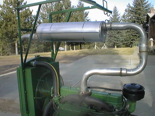
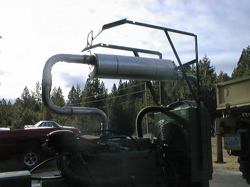
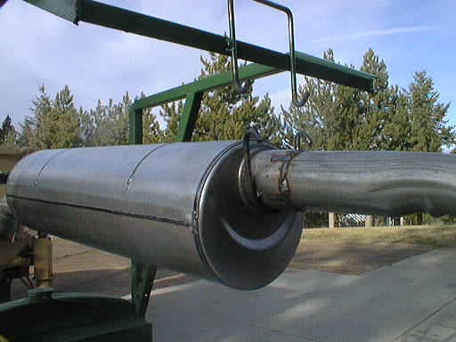
Out shopping today I bought an exhaust system. $150 at the muffler shop for the big-block Chevy motorhome muffler and four 3" pipe elbows. Using small-diameter muffler pipe for a support bracket was too expensive (another $60), so I went to St. Vinnie's and bought an armload of bed rails for $15. I should be able to weld up something out of all that.
The panel meter set I ordered was sold out, so I substituted two on-sale 50 VDC meters instead. I may be able to re-scale one of them to be my ammeter. For the voltmeter I'll just steal the Weston that I already have in a piece of homemade test equipment I acquired many years ago. Too bad, because the panel meter set had some switches and lights that also would have been useful for this project.
I carefully removed the exhaust system and welded all the joints. I put it back on the engine (with exhaust gasket this time) and it was still as it should be, so I fired it up. Quieter! The fan roar is still quite loud. There were no perceptible gas leaks from the welds.
Next I used the bed frame rails to fabricate a scaffold over the top of the muffler that bolts to the radiator support. (It's held on with vise-grips right now.) I bent (using the oxy-acetylene torch) the crib slider rods that I also got into hangers with hooks on them for rubber exhaust donuts, which I then welded to each end of the muffler, and I welded a mating set to the scaffold. I only have one of the four required donuts, so I'll get some more later. This scaffold is intended to relieve the exhaust manifold of some of the weight of the exhaust system to prevent (?) cracking due to weight and vibration.
While the rollaround cart was freed up, I cut off the solid rubber tires with the portable bandsaw. What a pain. The tires had developed flat spots due to the weight and the axle supports had also sagged a bit so that the tires rubbed on the top of the brackets as well. The poor thing basically couldn't roll anymore. I guess 6 330# wheels aren't enough for the weight of the generator. Without the tires to flatten and with a lot more space above the wheel it should roll again, at least easier than it did, though the metal wheels that remain are rough castings rather than smooth round wheels. I also painted the cart. Gray this time, I'm just about out of JD green.
Once the paint was dry(ish) I lowered the generator back onto the roller frame and towed it into the garage, again using the hook on the end of the extended crane as the tow point. That was a royal PITA, because it still doesn't roll very easily. Better than it did, though, and I was able to jockey it the rest of the way into place (in the aisle between the cars) by hand.
I then put the three gallons of antifreeze into it and fired it up to mix the coolant.
Finally I spent several hours cleaning up the garage bay so that I could put the 450 SL back away. Such a mess I made! The poor car won't be able to stay inside too long, because next I'm going to put the 190D in there for its tranny swap. But I rolled its windows down so that it could dry out at least (much condensation), and put the battery charger on it. The car did start instantly even though it has sat outside for nearly two months.
...Out shopping today I bought four new rubber exhaust hanger donuts at NAPA, and when I got home I installed them. There, all done except for enhancements. It's ready to use.
(While poking around with my test equipment I found that my POS 2336 Tek scope has lost focus. Last time it broke [and it doesn't get used that much] it lost HV, which was a big pain and a not-insignificant expense to repair. I used to be happy that I had this little scope.)
With this thing built I put it out on the generator's batteries, temporarily using alligator clips until I can get a proper wall-wart power connector. Ideally it'll jack into the side of the control box.
Next I took apart the Web TV box and cut the PCB apart giving me a DC power plug hooked to a bit of PCB with a mounting hole in it. Then I cut a piece of walnut (strong, insulating, and easy to work) to serve as a mounting bracket and mounted the socket so it was visible through a 1/2" hole in the side of the control box. Then I spliced the mating plug into the power supply (which incidentally made the cord longer though I didn't need it longer at the moment) and soldered two ring terminals on a hank of the same zip-cord wire that was in turn soldered to the PCB fragment for hookup to the batteries. I put this connection on the fused side of the +24 V bus, and to case ground. This will let the internal fuse protect this additional exposed wiring if something should damage and short out the external wiring.
Now the generator has a nicely-attached battery tender, so I can dispense with the alligator clips to the battery.
OK, here's the meter fantasy: 3-position phase selector switch that moves the main volt- and ammeters. 4-position auxiliary meter switch that switches the third meter among: phase wattage, total wattage, battery voltage, and line frequency. Can all this be done?
The Mac crashed hard today, it never came back up after a scheduled power outage. Even though my wife shut it down correctly. Weird, it's survived a lot worse! There will be a short delay while I reinstall everything...
I picked up another bathroom scale (fuel gauge) at the thrift shop. This one is superior in that it has a moving pointer rather than the more common moving scale, and even has four movable plastic arrow markers that I can set as Full/Empty marks for the two BBQ tank sizes I anticipate using. (20# and 100#.)
...One vote came back matching mine, and another was for the traditional bridge form (the corrected variation of what I started making). I picked the variation of the original representation (by the designer) that I made which I believe to be the clearest. I then began laying out the full circuit diagram. I still need to design the shunt-based ammeter function, and the frequency meter. It's looking like it'll be a pretty tight page if I want it all on one A-sized sheet.
It's clear that the combined schematic will be two A-sized sheets, if the eventual ammeter circuit bears any resemblance to the wattmeter circuit.
Anyway, I stole the crap battery from the 190D, for which I had bought a replacement anyway, and put it on to replace the deader. I opened the propane valve and flipped the ON switch. After a couple of seconds of cranking it fired right up. I then got out the big cable extension cord, turned off both generators, and made the switch. Then I fired the big one up again. Success! I had lights, so I went in and turned on all the 220 V breakers. (Especially the hot water heater.) The voltage was low, about 90 V, so I turned up the adjustment pot to get 120 V. No problem. The RPM wanders slowly, the frequency gauge will walk across its full range (about 6 Hz), but that's a minor issue. Nothing we have will really care much about that.
This is the first 'shot fired in anger' with this generator, I'm glad to see that it seems to be working fine. I can't wait for my shower!
...I got my shower. But we've had some voltage and frequency issues as the load changes, I heard the fireplace fan speed up dramatically and the UPS even took the computers off the generator. I think it happened when the water heater shut off. I got the voltage dialed back down, and later it looked like the frequency was back on track. I will need to look into it. When I shut it down to go to work (extremely late) the hour meter read 2, and the fuel gauge indicated that about 5 gallons had been consumed. Thirsty!
Another hot shower today! But the morning 1.5+ hour or so run sucked the tank dry, it pooped out just as I was finishing breakfast. Let's do the math. The hour meter is currently at 3.6 hours. Assuming the newly-installed hour meter on the generator was at about 0.2 hours, the forklift tank (which I filled today, 9.2 gallons) ran the thing two mornings for a total of 3.4 hours. (Plus a few short test runs and whatever minuscule storage leakage there is.) That's nearly 3 gallons per hour. Propane was $2.25/gallon today, so my showers were about $10 each! Steep. The generator wasn't even particularly heavily loaded, I can't imagine how hungry it must get when taxed to its limit. (Jill did get a shower for herself and a dishwasher run too, so the cost is somewhat amortized.) Not particularly economical, nor good for an isolated existence if you have to fill a tank every other morning. This is obviously not the right generator for our needs, but the price was sure right! We really need to plan our use of it to get the maximal value out of the fuel. I must figure out a way to replace it with something more suitable for our needs, then I can sell it. It's worth more than a few sheckels 'on the hoof'.
The power came back on at noon, so Jill switched things back over to normal. A relief, certainly, though I was kind of looking forward to being the generator hero for a few more days.
I put the main UPS on charge this evening. I tried charging it earlier off the rope-pull with the idea of trying to use it to coast through the night, but something about that power didn't please it: it would only operate from its battery. I'll need to look into that sometime, it may be set too sensitive to voltage or frequency for our needs.
I moved the extra diode string (for setting the voltage higher), the series blocking diode, and the output cable to the new wall-wart. (The wart's cable was too short and had the wrong connector on it.) I also removed the overvoltage crowbar Zener diode, as the increased output voltage would trip it and short out the power supply. (It's not needed, this thing is no longer feeding sensitive electronics.) I plugged the modified supply in and it worked, sending the new, higher voltage out the connector. I used two tie-wraps to hold the shell back together and took it out to the generator and installed it. The battery measured greater than resting voltage with it on, so I'm going to call the operation a success. I'll check back later after things have had a chance to stabilize.
I should probably procure another 24 V HP wall-wart the next time I run across one at the thrift store, it looks like these things don't last forever. There should be more than a few of them out there, inkjet printers are a very disposable commodity these days.
I'm also wondering if kVA (and by extension, Power Factor) meter reading(s) can be derived? The kVA is probably possible by using the multiplying wattage circuit but feeding it the averaged voltage (for the voltmeter) instead of the instantaneous line voltage. Power Factor is just W – kVA, subtraction is easy in the analog domain. Worth some thinking about, but the switching and meter faces could get complicated, and this board is starting to get large already.
(We're adding onto the house, and unfortunately the power feed to the house has to move. Since we've got to re-do the feed anyway now's the time to look at moving the meter and installing a cutoff switch.)
I am also reminded that power factor is not W – kVA, but W/kVA, which is a whole 'nother kettle of (bad-smelling) fish. (How embarassing.) Oh well, it's a dumb idea anyway, that board design is getting way out of hand already. Power factor is only of real use where long transmission lines are involved and resistive losses are to be controlled. With a local genset, the only thing you're really after is making sure the windings aren't overloaded, which is the kVA reading. If I really care about power factor I can just tether a calculator (or slipstick) to it!
Since I was in the area I finally remembered to stop by the propane shop and get a 2' length of reinforced 5/8" fuel line to replace the temporary heater hose between the carburetor and the evaporator. $6. However, now that I check my records it looks like maybe I do need 3/4" hose, which the guy had suggested as being what I'd probably need for an engine of that size. Oops! It was a calculated risk, and I'll know for sure when I get out and actually measure what's there now. He did say that the only danger of using heater hose is that it would get soft and suck flat, and that courtesy of the way the fuel vaporizer works it wouldn't leak propane. That's good, I've been a bit worried about it.
Also, the propane hose I needed for the carburetor was definitely 3/4", not the 5/8" I bought yesterday. Oh well. Batting .500 since I got the length right? Hah!
However, even after being well heated up nothing came out of the tank, and there was no more sloshing. Perhaps it was propane, but it leaked out since yesterday? Oh well, onwards. I took the top handle/guard off and straightened it a bit with the hammer. I then wire-brushed everything and got off all the dirt, then masked the fittings and sprayed on a coat of primer. Looks a lot better.
...At lunchtime I returned the core battery.
Your unit has a mechanical flyweight governor that is either belt or gear driven. It's probably a Hoof, Pierce, or something comparable.Rumor has it that you set the generator to about 63 Hz at no-load, and it'll drop to about 60 Hz at full load. That is 'normal' for this class of machine.You can use the Google to get more information on the Hoof governors, as the operation is pretty common amongst all mechanical governors.
You'll have a speed control screw or adjustment and a sensitivity adjustment. The sensitivity adjustment usually consists of a lever or bolt with the end attached to a spring. By lengthening or shortening this bolt, you change the sensitivity or gain of the governor. This determines how sensitive the governor is to changes in engine speed.
In your case, I suspect your governor sensitivity is too high, meaning that even small changes in engine speed will cause the governor to react. As a result, the engine speed is unstable or oscillates for a while after the change takes place. It's possible you have fuel system problems, but absent that, the governor is the most likely culprit.
There are some really detailed instructions on the following web site:
If you put the term "governor" in the search box on their home page the first hit will be "Tech tip #182: Foley Universal Governor Installation Guide".
It ran! No muss, no fuss. The frequency was a little high, 64Hz, and as a temporary expedient I wedged a bit of paper into the mechanism to shim the throttle rod length a bit, and got it to 60 Hz. That made the UPS's much happier.
The 1/2 full tank ran the hour meter from 3.6 to 5.4, before it ran out. I put the other full tank on. We were heating water, doing laundry, bathing...
The hour meter ended at 8.6 hours. We used 1.5 tanks of propane to run just about 5 hours. Sigh.
The tank ran the hour meter to 11.4. 8.3 gallons of propane, 2.8 hours. Still right at 3 GPH. Sheesh.
Firing up is now slightly more complex, you just have to remove the two chargers and put the batteries back in series, then go.