When we got the Chicken Wagon most everything that wasn't critical to forward motion was broken. No surprise that this included the cruise control, as MB's are notorious for this failing.
I had fiddled with it a little bit around the time of purchase, but had gotten nowhere. It seemed apparent to me that it was the amplifier module, as this is the common failure point. I pulled the module and it sat on my workbench for a long time, glaring balefully. I had done some work to ensure that the switch, wiring, and actuator were apparently OK, so all I needed was the time and motivation to tear into the amplifier.
Well, we made a road trip recently in the SDL, which has a stunningly good cruise control. Until recently that is. Now it's acting spastic. It starts out OK, but as it warms up (?) it starts to jerk on the fuel, which is extremely annoying. Eventually it cuts out altogether. It is obviously developing electrical faults, and it needs to be fixed before we can use it again. I had already lubed the linkages, but I didn't really expect this to do anything. (It didn't.)
Well, hello motivation! One of the reasons for procuring the Chicken Wagon was to serve as a testbed and training ground. I mean, if you can't rip into a $400 car with no fear, what can you rip into? I need to learn more about fixing these things. (I have had only fair luck at fixing cruise controls up 'til now.)
This resolve didn't do me a great deal of good, however. I had been trying to accumulate enough extra cruise control parts so that I could assemble a system on my workbench. This is much more conducive to involved ripping and tearing, as compared to laying under the dashboard of a car. But until this week, all I had was the stalk switch, some connectors, and a bit of wiring harness. (I am obviously slow when it comes to getting at the hulks at the U-Pull. Plus, they tend to be old. [I do have a couple vacuum-operated cruise control systems.]) No spare amplifiers, no spare actuators.
Well, Hallelujah! There was a 1985 190E in the U-Pull, and the servomotor was still there! Very hard to get out from its nest under the intake manifold, but I was eventually successful. And only $8! Now I finally had all the parts I needed to assemble the system on the bench, and I had the motivation to do it. I had also recently cleaned off the bench, so it was time!
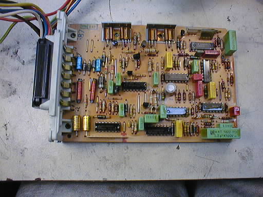
I should mention that in a much earlier session I had already determined that the single electrolytic capacitor can on the board was not in great shape anymore, and I had replaced it. No material change, unlike the 450 SL's vacuum-operated cruise control. Replacing this single capacitor was made very difficult by the PCB's conformal coating of varnish.
The replaced electrolytic capacitor is in the middle of the board, the gray-rimmed aluminum circle almost directly below the rectangular yellow capacitor, between two of the integrated circuits. (In line with the rightmost of the four heat-sinked power transistors.)
I assembled all the parts on the workbench and started hooking things up. One problem: the speedometer signal! Well, here is my virtual car:
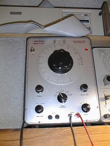
Not too difficult, and this might represent my first actual use of this old piece of test gear. (It's sitting next to my Heathkit capacitor tester, and underneath my old 68010 In-Circuit Emulator.)
After some fooling around with signal generator settings and the stalk switch, I got some sign of life out of the actuator. It didn't act right, but after enough messing around I got it to stay 'engaged', at least for a bit. I start probing around with the oscilloscope, just for grins. What I found after a lot of fooling around was that the actuator would abruptly disengage if the board was flexed a small amount in the wrong direction. Bad connections! There are three possible sources of this problem, and I was really hoping it was bad solder joints rather than cracked traces on the PCB or (even worse) defective connections within components themselves. (I've seen all of these in my life.)
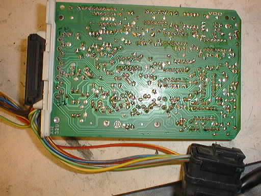
Remember the conformal coating? (The board had been dipped in varnish to seal out moisture.) This completely interferes with clean soldering, and it had to be dealt with before any serious repairs could be attempted. I tried Methyl-Ethyl Ketone. Nothing. So I got out the paint stripper. Scary stuff, I was afraid it would eat the board, but this is the Chicken Wagon and fear is not acceptable!
I carefully brushed it on the back of the board, being very careful not to get it on the components. I didn't want the legends to be eaten off, especially if I had to replace parts! After a suitable wait all the varnish crinkled up and I was able to scrub off the goo with a bristle brush and hot water. The board cleaned up nicely, and the stripper didn't even seem to bother the solder mask. It looks good!
I noted that some of the joints had that crystalline look that is characteristic of cold solder joints. This was a lot less apparent with the varnish coat in place. It looked like there was some room for improvement (which I already knew due to the flex test.)
So I blew off the board with compressed air and set it on a light to finish drying. After some drying, I hooked it up again to test to see that the board still behaved as it did before. It did.
So then I resoldered all the joints on the back side of the PCB.
An interesting and disturbing thing about the process was that as I heated many of the connections they would bubble. And they kept bubbling so long as the heat was applied! Either the board had a wicked case of contamination, or, more likely, the conformal coating remaining on the component side had trapped air underneath components that would bubble out the through-holes with heat. The problem was worse on the DIP IC's and some of the larger square capacitors. I had to re-solder many of the connections to get the worst of the craters out of them.
Finally I inspected the solder job and then hooked the board back up. It behaved as it did before, but without the change in behavior as I flexed the board. I set the board up on the light to continue drying (just in case), and to give it a bit of a thermal test (nothing extreme).
I then started playing with the controls more, especially the ones on the signal generator. I found a point where the throttle arm on the actuator held a center point. If I increased the frequency of the generator a little, the arm would move to reduce the throttle. If I decreased it a little the opposite would happen. It's working! And, there is no sensitivity to board flexure.
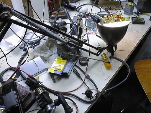
Here is a picture of the whole setup on the workbench. If you look at the throttle rod sticking out the side of the actuator, you'll see that it is roughly parallel with the workbench surface. This is being held there by servo action, I could wave the rod up and down using the frequency knob of the signal generator. I could also get the expected actions out of the cruise control stalk switch. This puppy was ready for a road test!
I slid the board into place and we went for a drive. We needed to go to the hardware store anyway. I got on the freeway, got up to speed, and hit the button. It worked! It surged a little, but settled down after a bit. The controls operated somewhat as expected.
But not nearly as smoothly as the SDL. On the other hand, I'm not all that surprised. The Rube Goldberg throttle linkage that the Chicken Wagon has is nothing like the clean direct shot the actuator has on the SDL. If you pull on the servomotor actuator by hand, you can feel quite a change in resistance as the linkage moves over its range. (It's easier at higher throttle positions.) That can't help.
Also, I note that at slower speeds in the 40–45 MPH range it surges a lot. Enough to make such a journey unpleasant. Not of great concern as all cruise driving around here is at 65 MPH plus, where it works fairly well.
There may be some design differences between '83 and '86. The CC won't resume properly unless you're already near the target speed. And sometimes it just won't resume at all, you have to re-set the speed. I don't really know how this particular control is supposed to operate, so I don't know if it needs further fixing, or whether it's supposed to be this way.
On the other hand, it works, and I'm disinclined to mess with it further. It would be fine for a freeway trip, and that's what it's for.
As a parting shot, I cleaned and lubed the entire throttle linkage, and even managed to take some play out of it by shimming a bearing. But it didn't seem to make any difference.
More recently I came across a schematic for this cruise control, which might help.