When I purchased this car, as an engagement present for my then-fiancee (now wife), it needed a lot of work. As part of this work, I had taken the driveline out. (Replacement transmission and a new differential pinion seal.) As is well known, even by me, you need to mark the two-piece driveline so that if it should become separated it can be reassembled in its original orientation, presumably preserving its state of factory grace, I mean, balance. Unfortunately, while I did mark the driveline, I didn't do it well enough. The marks came off!
Crap. Memo to self: Next time use paint.
By this time in my life, I had lost my job. I had the gift car, and most of the repair parts already purchased. I had plenty of free time, but no income, so I wasn't interested in spending any extra funds if I could help it. I could easily have the driveline reassembled and rebalanced, but this wouldn't have been cheap. And the delay in shipping it off (to Portland) didn't fit in well with my plans. I was already late in putting this car together.
So as so often happens in this case, I merely reassembled the driveline and hoped for the best. At least I tried an (un-?)educated guess for its alignment, assuming that the drive ears would at least more-or-less align, which cut my chances of getting it right to one in three rather than one in twenty or so. (To be fair, it's probably no more critical than one in eight.) And, I believe I made some deduction based on where the balancing weights were on both pieces. My final choice of alignment wasn't arbitrary, but was it right?
Finding out whether I got it right or not was complicated by the fact that the car had been extremely noisy when I got it, all the rubber under the car was pretty much shot, and the transmission whined as well. So, I didn't know whether or not there had been any original driveline noise, the car had an obviously-checkered past and could have been screwed up by that time. (Other things certainly were.)
Anyway, time proved that the driveline wasn't totally happy, there was an obvious, though not serious, thrumming at freeway speeds. This is usually a driveline problem. But, it wasn't enough of a problem to warrant tearing into the car again just for that.
Time marches on, though, and after 3+ years the car needed another session under the knife. The exhaust system was full of holes, and taking this off is a big step on the way to the driveline. So, while fixing the exhaust system I decided to take another whack at the driveline. I had never replaced the original (?) differential mount, so part of the plan was to replace this last bit of rubber. Also, the rubber ring that supports the center driveline bearing (both new parts in the original session) was already torn. So it gets replaced too.
But what to do about the unbalanced driveline? I still didn't want to send it off to Portland, spending a bunch of money to correct my own stupidity. Not if I didn't have to.
The car was already jacked up. I took off the rear wheels, and used lug nuts (with some other large nuts as spacers to keep them from going in too far) to hold on the rear brake drum/disks. I rigged an old cruise-control cable to the throttle linkage, using a small pair of vise-grips. I snaked the cable down below so that it stuck out by the transmission.
Now I could lie underneath the running and in-gear car, and watch the driveline as I rev it up. Boy, was that fun! I was wearing earmuffs because there is no exhaust system, but the car was blatting nice hot smelly exhaust at me anyway. It was so loud under there that there was no way I could detect any driveline problems by ear, and by eye there was nothing overtly wrong, even though there clearly was something wrong on the highway. Not to mention the extreme difficulty there would be in trying each of the possible driveline orientations, nor my nervousness at lying under there to begin with, in spite of every failsafe mechanism I could dream up. (I even had my anvil under there as crushproofing insurance.)
This wasn't going to work.
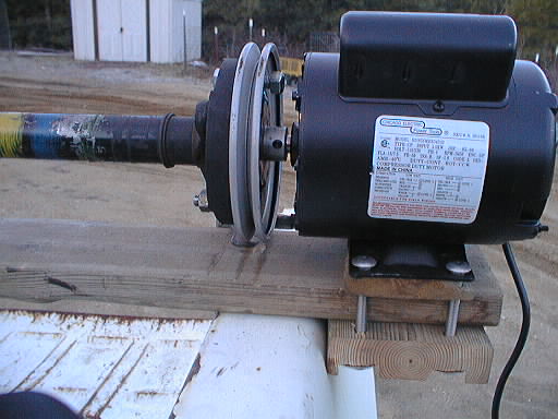
I had noticed that the driveline's centering pins were almost exactly 5/8" in diameter. Hmmm, many electric motors have a 5/8" shaft! I went to Harbor Freight, and bought one of their 2 HP 3450 RPM motors on sale for $60. (I have other plans for this motor anyway.) I wanted a 3450 RPM motor rather than the more common 1725 RPM motor, because this corresponds to around 70 MPH on the road.
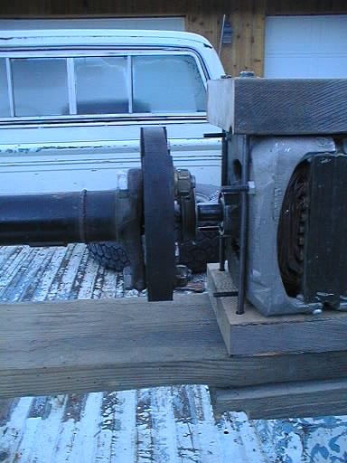
That takes care of one end, but what about the other? Another motor would be easiest, but I don't need a working motor, so I go down to St. Vinnie's (St. Vincent de Paul thrift shop) and snoop around in their junk shop. I find a washing machine motor that has good bearings, but a 1/2" shaft. (It probably works fine, but who cares?) I purchase it for $2, and stop by a bearing supply house on the way home to get a 1/2"–5/8" bronze bushing. Another $2 or so. I stopped at a hardware store and bought a 7" pulley. ($18, Yoiks! But this also will be useful with the motor in the future project, so I'm not too worried.)
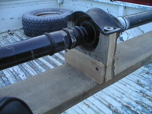
That's all the hardware I should need. I have plenty of bolts, screws, and such laying around already, and lots of wood. I grabbed one of the 2×6 planks I use as parking stops in the garage, and some 2×6 scraps leftover from construction. I made some wooden spacers to put the two motors at the right height off the plank, with their shafts concentric. (The thickness planer came in handy.) I made a wooden collar of the right height to hold the center bearing securely with the driveline straight. (Bandsaw, very nice.) Using leftover bolts, I clamped the two motors to the plank, spaced so that the driveline could be compressed and just slipped out from between the motors. (That should help make trying various orientations easier.)
We're almost there. I wrapped one non-overlapping layer of masking tape around each 5/8" motor shaft. This takes out all of the slop in the joints, since the (metric?) holes in the ends of the driveline are slightly larger than 5/8". I then bolted the rubber flex disks to the driveline, mounted the driveline in the lathe, and then drilled through the three open holes of the pulley-end flex disk into the pulley. Then I bolted the drive-end flex disk to the pulley. (The other end isn't bolted to anything, and is just friction fit onto the motor shaft.)
Time to fire it up. I used two C clamps to hold the plank to a couple of cinder blocks so this flying deathtrap won't get loose. Contact! BrrrrrrRRRRR-CRACK! Holy crap, unplug this thing quick!
That cheap (but not inexpensive) POS new pulley broke, and postmortem examination showed that it had been very poorly spot welded together. So out came the wire-feed welder, and I really nailed it back together good. It wasn't perfectly straight and had a slight wobble, even to begin with. Clamped tightly to the driveline, it had too much off-center stress on it and had split. Also, the bushing on the other end had slipped into the driveline so that end was wobbling on the 1/2" motor shaft, and the wooden support for the center bearing had cracked. Not a very successful first flight.
But par for the course. I glued and reinforced the wooden support, and pinned the bushing to the (already drilled) 1/2" motor shaft. Besides welding the pulley, I rethought the desired goal, and decided that there was no need to tightly mount the flex disk to the pulley. I only wanted to spin it around, so leaving the three bolts somewhat loose was just fine, and reduced the stresses on everything. (After all, though this looks like a lathe, most lathes are built a little bit more substantially than with a single 2×6 plank! Not to mention with a bit more precision as well. However, I think it's a pretty good analog of life in the car, since things are free to move about a little there.)
After the glue dried, I clamped the plank to the bed rails of my beater pickup truck. This is more substantial than a couple of loose cinder blocks, and also holds things at a convenient working height. This round is more successful, the motor spins up nicely. Turns out the pickup bed idea is a good one, because the whole bed is serving as a sounding board. There is a pronounced vibration. (Very little with just the motor/pulley spinning.) Now to see if there's anything we can do about it.
As I mentioned before, there's probably only about eight orientations that you have to try. I tried 180° from the original mis-orientation (marked with black paint this time), and also at 90° and 270°. It seems that the vibration is substantially less at the 90° mark.
At this point I ran out of time, and will have to pick it up later. But it looks like I'm on to something. Not only is it easy to try various orientations, it will be very easy to try out some hose clamps as adjustment weights to see if I can reduce the vibration even more. However, it is now clear to me that the assertion of some, that the driveline orientation doesn't matter, is wrong. At least sometimes.
I was getting some inconsistent results, and it turns out that I wasn't controlling all the variables properly. As it happens, the orientation of the driveline assembly itself to my drive pulley mattered. Of the three possible orientations, one was substantially smoother running than the others. Every time I shifted the driveline assembly, I ended up with a random choice of the three pulley orientations, which was polluting my results. Once I figured this out, I paint-marked the pulley and driveline so that I could always assemble it the `best' way. Then I repeated the testing. This time, the results were more repeatable. I found that it did matter down to the individual spline level where I had the driveline assembled. I walked the alignment across every possible setting through my already-selected best octant, several times, and there was one spline position that seemed best. This final alignment was at approximately 110° from where I had guess-assembled the driveline in the first place. The mounting ears do not line up, nor do the weights welded onto the shafts bear any particular relationship to each other, so my original deductive process was flawed.
So, I spray-painted the driveline black, to cover up all the barren spots on this well-traveled item, and then paint-marked the two halves of the driveline using nice globs of fluorescent red paint. And set it aside to dry. Now I'm just waiting for parts to arrive so that I can reassemble the car. Only a road-test will prove whether or not I have actually fixed the problem.
It worked! A couple of short trips on the freeway have shown that the driveline vibration (a thrumming) is gone. I'm so happy.
Pictures:
Return to Site Home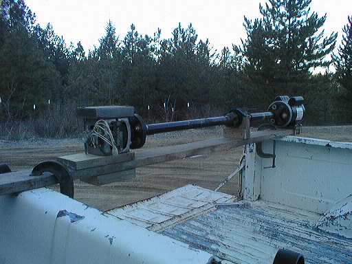