At this time it was apparent that the amplifier was (as is so often the case) broken. However, these are often easy to fix with a soldering iron. Also, age takes its toll on the aluminum electrolytic capacitors in the circuit. These particular parts are notorious for causing age-related failures.
So, I opened up the amplifier for a session. Looking at it I could see one of the dreaded aluminum electrolytics in the rough center of the board. I removed it, and tested it in my capacitor tester. While it still had a tolerable capacitance, it measured very lossy when compared to a new one. So I replaced it. As it turns out, this is a very important component, because it is the power supply filter for most of the sensitive analog circuitry. If it can't filter well, parts of the circuit start interacting where they shouldn't.Amplifier Variations.
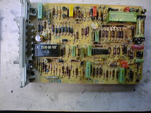
So far I have identified three separate variations of the early VDO cruise control amplifier, for vacuum-servo based systems. The first model has a gray connector, and a long PCB. It is fully stuffed with components. It is capable of remembering the set speed even while the car is turned off.
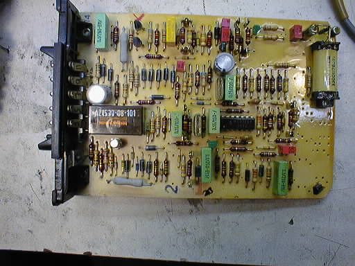
The second variation is similar, but has a black connector. The components responsible for remembering the set speed while off are not installed. (The 'shine' on the righthand side of the PCB is the protective varnish dip, which is used to prevent moisture from getting to the sensitive analog circuitry. More later.)
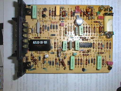
The third variation is similar to the second, but has a shorter PCB (and aluminum case). The area for the key-off speed memory components has been deleted, and a few of the remaining components have been rearranged. (As before, the 'shine' on the upper-right corner of the PCB is the protective varnish dip. Apparently they felt that only this area was sufficiently sensitive.) This is the amplifier used in this particular car. The extra resistors hanging off the front are the result of some of my efforts to 'tune' this amplifier's response to the car.
All three amplifiers have a 'flying lead' circuit connection in the upper righthand corner of the board. This connection is between the high-quality capacitor that's used to store the set speed, the FET amplifier that isolates this capacitor from the feedback circuit, and a relay that's used to actually set the speed. Because of the extreme sensitivity of the FET amplifier, the connection is made up in the air so that leakage currents in the PCB itself (normally minuscule) don't cause drifting of the set speed. Do not screw around with this part of the circuit, because this FET is hard to find a replacement for. And it's very sensitive. If I recall correctly, they used to ship these components with a shorting strap around all the pins. You removed this after it was soldered in-circuit. Anyway, the set speed is stored as a delta from approximately 60 MPH, since the voltage that represents speed roughly corresponds to the VCC/2 value that is the voltage the loop amplifier is designed to hover around.
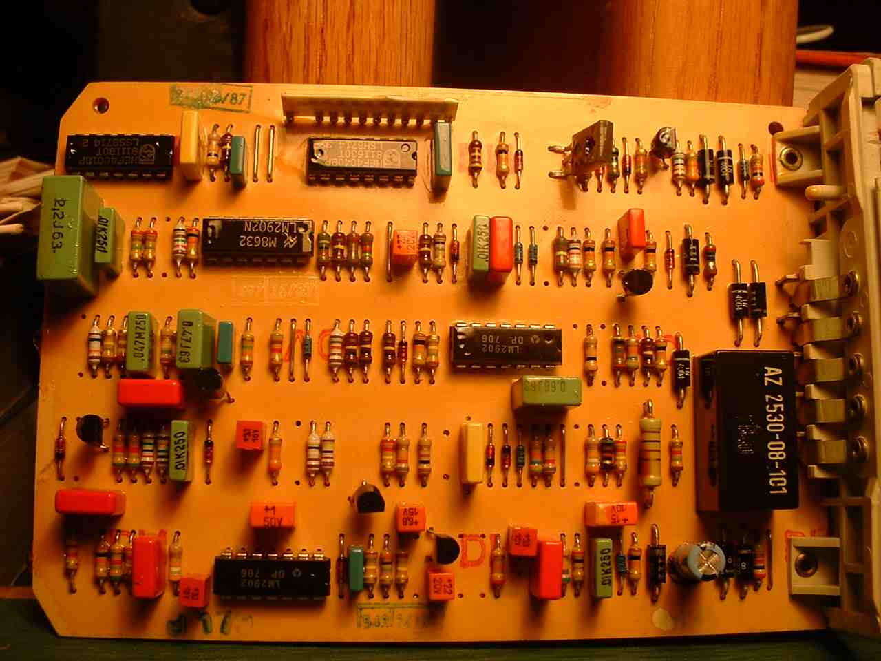
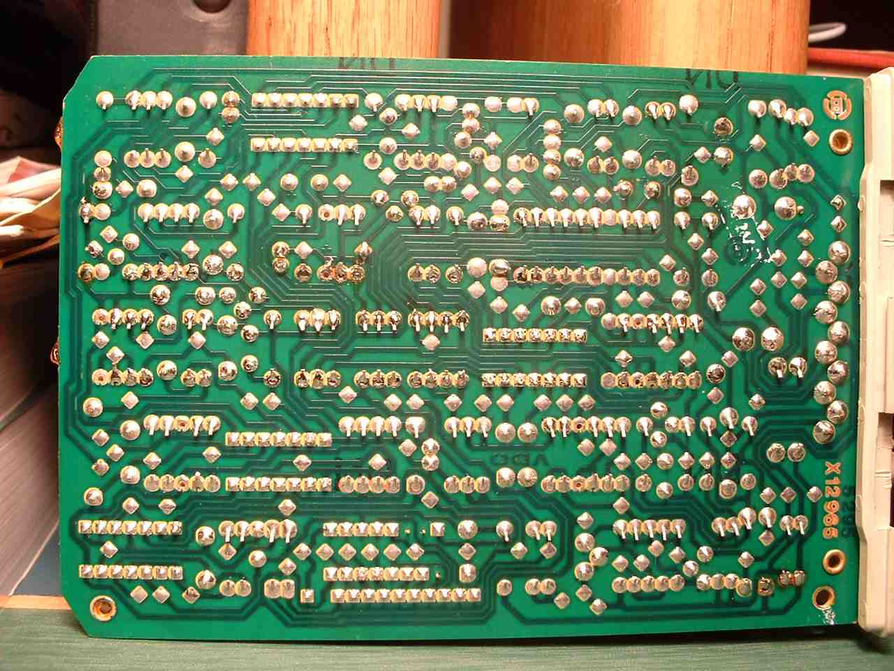
I have since been shown a fourth variation, [rear view] which uses the digital circuitry of the later servomotor-based VDO cruise control instead of the FET circuit, though it is of course for the vacuum PWM actuator instead of a servomotor. This is an odd beast, sent in for repair, and the date codes indicate that it is from the 1986/1987 era, long after mainline production had shifted to the servomotor system. Somewhat surprisingly, it doesn't have the stake-mounted tunable resistors of every other amplifier I've examined, whether vacuum or servomotor. It was found in a 1979 300 TD. I suspect that this is a rather rare item, produced as a factory repair part long after the FET circuit components of the original design were no longer available. I have myself never seen this unit in a car. If I understand correctly, Mercedes required vendors to be able to supply production on demand for 20 years after initial delivery, as repair parts. VDO was probably not happy that the demise of certain critical parts used in the amplifier necessitated a redesign in order to meet this production requirement. (They probably hoped that Mercedes simply wouldn't place another order for these amplifiers, and when that hope proved futile they detailed some poor sap of an engineer to design one! However, it may have been an existing interim design that was never really produced before, at least not in the US market, so the impact would have been less.) This theory of mine is completely unsubstantiated, of course.
I have since found a fifth variation, circa 1981, making it probably the fourth variation chronologically, which appears to be a version of the short-board black-connector analog circuit. The components are substantially rearranged, both tubular electrolytic capacitors are in the center of the board. It also uses an 8-pin TAA2765A "dual open-collector op amp" in addition to an LM2901, which is more like the original power-off holdover circuit, yet I don't see the large high-quality electrolytic (C25, 10 µF) that is responsible for actually remembering the speed. Not sure what the 2765 is for, the original circuit uses only one amplifier in the holdover circuit, yet this board uses both amplifiers for something. This board has five tuneable resistor sites, versus the six of an earlier board.
(I am told that Porsche used a very similar amplifier through about 1986. I have seen a photograph that certainly looks familiar enough, complete with the flying-lead FET and associated relay. Same connector block, etc.)
The other aluminum electrolytic, found only on the first and second model amplifiers, is not nearly so critical. (It's next to the connector in the photographs.) It probably doesn't need to be replaced, although you can if you wish.
At this point, I installed the amplifier back in the car. It worked! Well, sort of. While it now acted like a cruise control, it surged. Badly, or at least extremely annoyingly. This was somewhat discouraging, and the car stayed like this for a long time, over a year, due to the many other demands on my time. As a family of three now, it's not like we're taking long trips in this car anymore.
The cruise control surged, except when it didn't. That is, sometimes it would act a lot better than others. At one point, I noticed that if I kicked the amplifier its behavior would change. Aha! Intermittent behavior! This can be diagnosed on the bench.
Failed electrolytics are only half of the problems that plague these amplifiers. Bad solder joints are most of the rest. With age and vibration, the joints open up, and the amplifier stops working. It is difficult to see this problem, due to the conformal coating (varnish) that is on the board to prevent moisture-induced leakage currents and oxidation. It is also difficult to repair the problem, for exactly the same reason. However, this varnish is very easy to remove with paint stripper.Bench Vacuum Supply
After a session of fixing the later servomotor-based VDO cruise control in the Chicken Wagon, I had accumulated enough parts and tools to recreate its cruise control system on the bench. To fully recreate the vacuum-based system on the bench one more part was required: a vacuum source. (I already had several spare amplifiers and vacuum servos by this time.) Trying to pump madly with a MityVac at the same time you are troubleshooting the circuit is ridiculous. While you dont need a vacuum source, it's very nice to be able to actually see the servo's reaction to stimulus.
The same junkyard 1985 190E that supplied the cruise control servomotor for the first recreation also yielded a central locking system vacuum/pressure pump. (The later such pump, that can be operated from either front door or the trunk is the one I'm referring to. The earlier system pump, operated from the driver's door only, is completely different and would be very difficult to adapt to this purpose. I should know—I tried!)
Anyway, this pump can be forced to continuously run in the vacuum direction only. By opening the unit and wedging a piece of paper into one of the two relays that runs the motor, you can force the motor to always run. Experiment will quickly show you which relay to wedge, one makes pressure and the other makes vacuum. I hooked the pump to a variable power supply and set it to 12 V. It ran and sucked a vacuum, but it was pretty noisy. By setting the current limit on the power supply to 1 A, the pump would barely tick over while maintaining a 5" vacuum, which is enough to run the cruise control vacuum servo. And it barely makes any noise while doing this.
I have since made a different vacuum pump using that much-less-desirable unit from an early 126. It was more work, but provided a worthy home for this POS. In its foam football it's fairly quiet, and can also be turned down (from full speed) on the bench power supply.
What I did was to carefully apply a Methylene Chloride-free non-drip stripper to only the bottom (circuit) side of the board. You do not want to get it on the component side, where it will at best remove the labels from the parts, or at worst destroy the relays! I recommend painting it on with a brush, but from the underside. That is, let gravity help keep the remover from migrating to the wrong side of the board. Then you just keep an eye on the progress of the stripper. When the varnish is all wrinkled up you can wash off all the crud. I used running water and a bristle brush to clean the board, followed by an alcohol wash to get off the water, followed by blowing off the alcohol with compressed air. This leaves the board clean and dry and ready to solder. Try not to get the relays wet, as you don't want water to lodge inside their guts, where it can corrode the switch contacts.
I then carefully resoldered all the connections. This is tedious.
An interesting and disturbing thing about the process is that as I heated many of the connections they would bubble. And they kept bubbling so long as the heat was applied! Either the board had a wicked case of contamination, or, more likely, the conformal coating remaining on the component side had trapped air underneath components that would bubble out the through-holes with heat. The problem was worse on the DIP IC and some of the larger square capacitors. I had to re-solder many of the connections to get the worst of the craters out of them.
At this point I connected (back) up the on-bench version of the cruise control system. It appeared to work fine, so I put it back in the car.
It still surged! But another spare amplifier I had been playing with (ultimately destined for a retrofit to the Ebola Fishtank) didn't surge (though it had a problem with a slowly-sinking set speed, and I suspect FET damage). Back to the bench.
What I noticed on the bench, using an oscilloscope to monitor the PWM signal to the vacuum servo, is that the non-surging amplifier had a definite 'kick' in its reaction to a simulated slowdown, whereas the surging amplifier did not. Its PWM signal was directly proportional to the speed difference from the set speed.
In the schematic I had been sent by some kind soul, the right-hand side of Figure 2 is the servo amplifier. I believe it implements a basic PID (Proportional, Integral, Differential) type of servo feedback loop. The capacitor C18 (10 µF, near the FET) causes the output of that section of U1 to change its reaction over time. Theorizing that this capacitor had a bad connection, I removed it from the non-surging amplifier. This amplifier now exhibited the same proportional-only PWM response as the surging amplifier. So I reinstalled C18, and then really went over the solder connections in this area on the failing amplifier.
After this, the board then exhibited the 'kick' in its PWM response, and when installed in the car, worked well!
Since this, I have been tinkering with some of the trimmable resistor points on the PCB to try to learn what they do (relative to the car's behavior), and to try to optimize the behavior of the cruise control. But I have learned nothing conclusive yet. The best way would be to repair one of my spare amplifiers and then replace these resistors with potentiometers, make an extension cable so the amplifier could lie in the passenger seat, and then go for a drive while I fiddled with the knobs. But that might be some time away!